Tunnel bottom structure and construction method capable of eliminating uplifts of inverted arches of tunnel in area with high ground pressure

A construction method and high ground pressure technology, applied in tunnels, tunnel linings, underground chambers, etc., can solve the problems of unfavorable tunnel bottom structure and unfavorable ground stress dissipation, and achieve the elimination of hidden safety hazards, remarkable economic and environmental protection, and convenient and compact construction procedures. Effect

Active Publication Date: 2018-01-26
CCCC SECOND HARBOR ENG
View PDF18 Cites 3 Cited by
  • Summary
  • Abstract
  • Description
  • Claims
  • Application Information

AI Technical Summary

Problems solved by technology

[0004] The purpose of the present invention is to solve the problem that the prior art tunnel bottom structure mentioned in the above background technology is not conducive to the discharge of groundwater and the dissipation of ground stress, and to provide a tunnel bottom structure that eliminates the uplift of the tunnel in the high ground pressure area. and construction method

Method used


Image

  • Tunnel bottom structure and construction method capable of eliminating uplifts of inverted arches of tunnel in area with high ground pressure
  • Tunnel bottom structure and construction method capable of eliminating uplifts of inverted arches of tunnel in area with high ground pressure
  • Tunnel bottom structure and construction method capable of eliminating uplifts of inverted arches of tunnel in area with high ground pressure

Examples


Embodiment Construction

[0027] The present invention will be further described in detail below in conjunction with the accompanying drawings and specific embodiments.

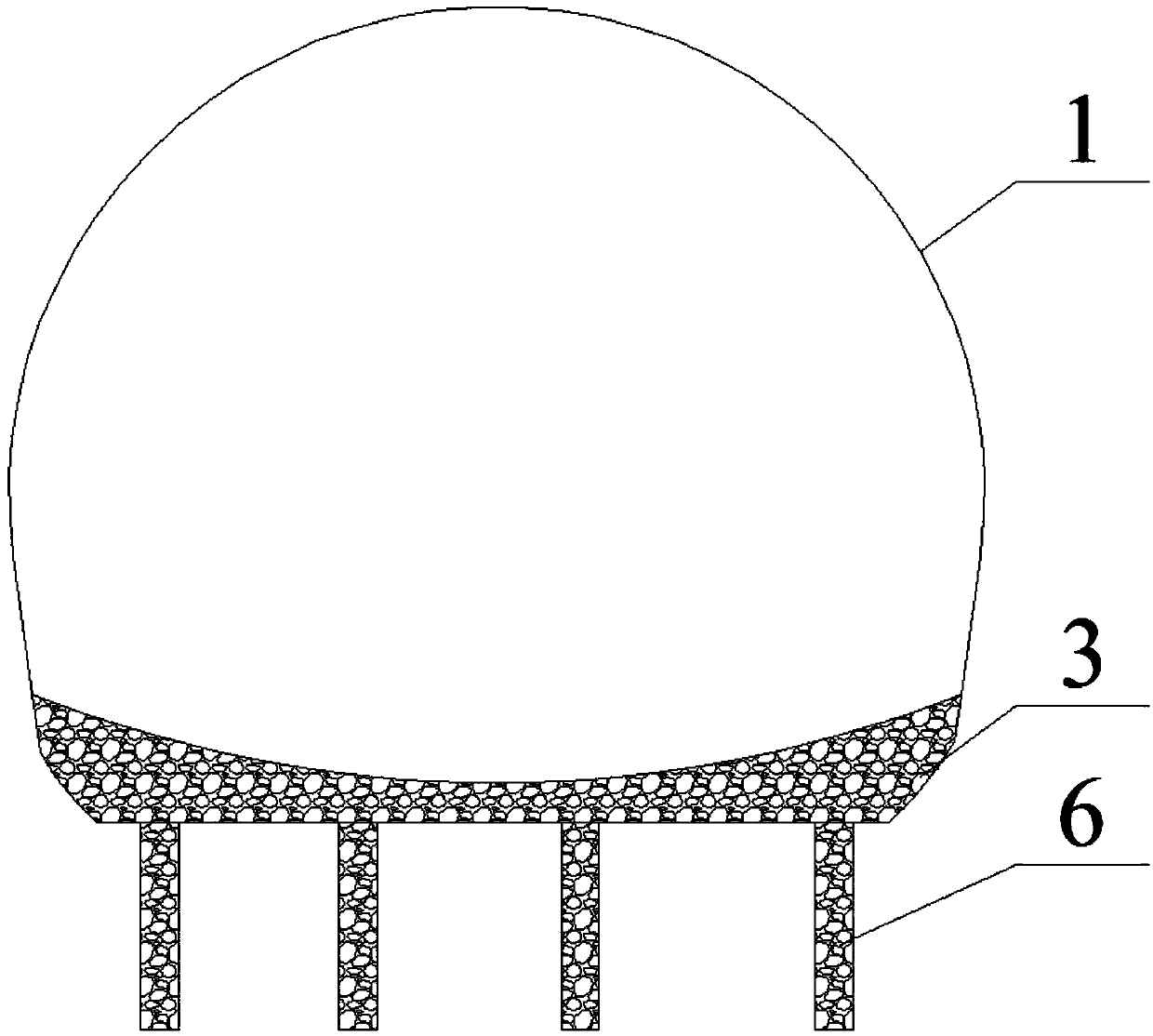
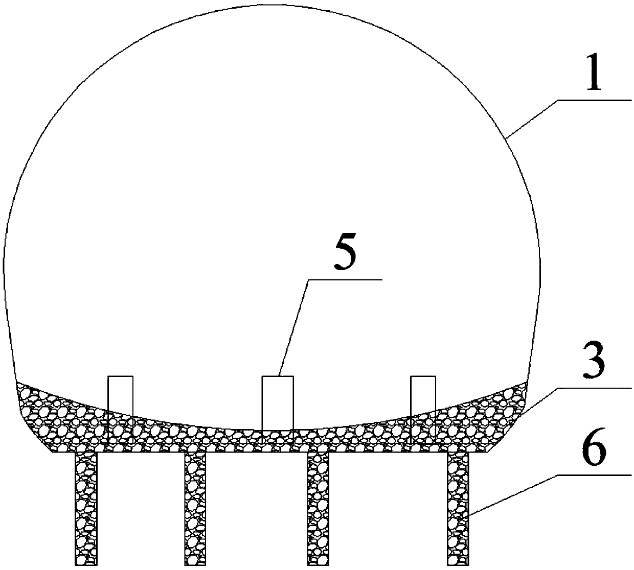
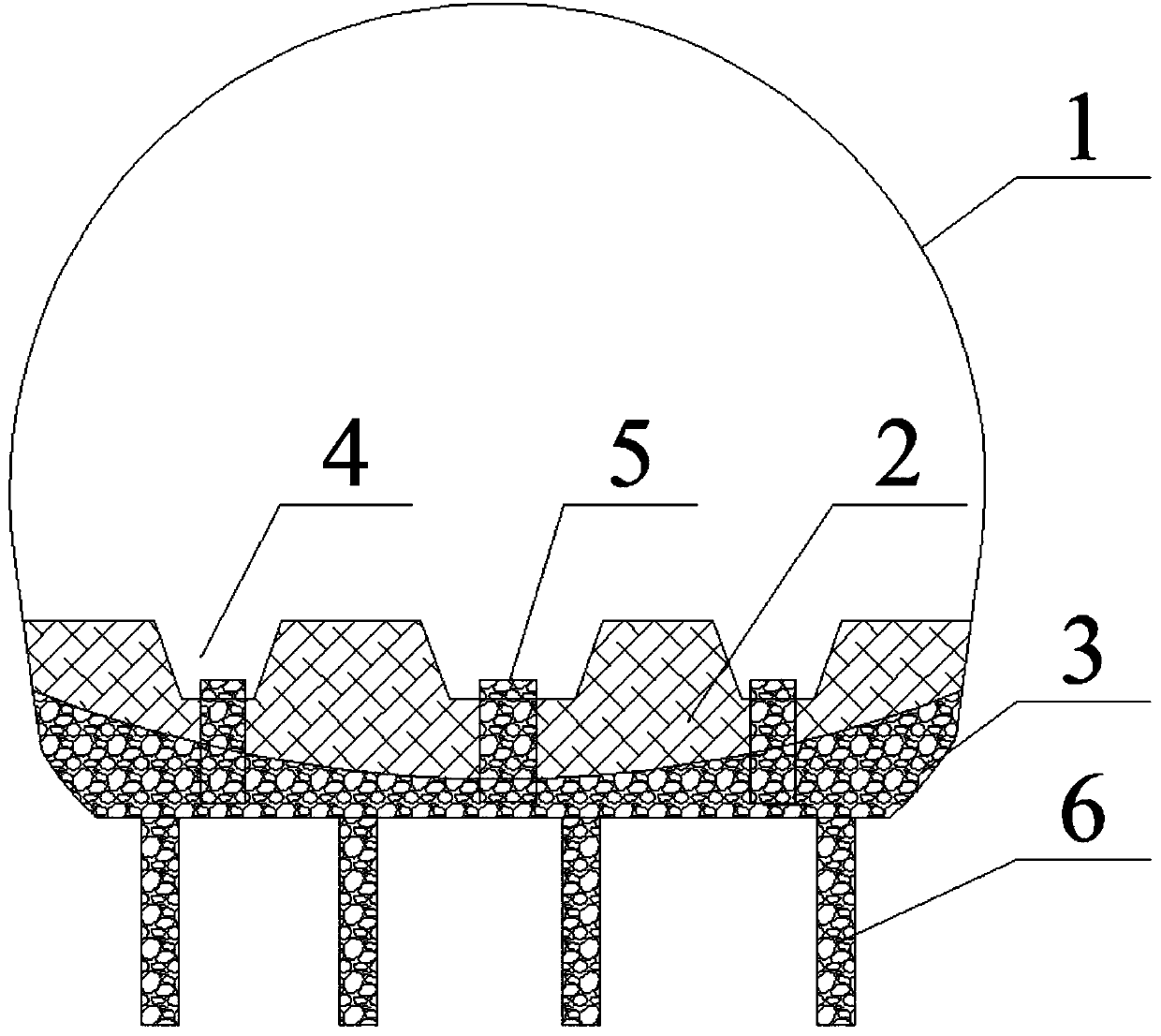
[0028] Such as Figure 1~3 , a tunnel bottom structure that eliminates the uplift of the tunnel invert in the high ground pressure area. After the initial support 1 of the tunnel is completed, excavate below the design area of ​​the invert 2, and excavate 40-60 cm downward to form an over-excavation backfill area. This part of the over-excavation backfill area is used to backfill gravel to form an over-excavation backfill layer 3. A support layer with many pores can be prepared by filling gravel. The pore structure can effectively dissipate the ground stress. In addition, the pore structure can discharge groundwater through capillary phenomenon. Avoid excessive water pressure and damage to the inverted arch 2.

[0029] In order to quickly discharge the groundwater in the surrounding rock below the tunnel bottom, the present embodimen...


PUM


Abstract

The invention relates to the field of tunnel defect rectification technology structures, in particular to a tunnel bottom structure and a construction method capable of eliminating uplifts of invertedarches of a tunnel in an area with high ground pressure. The structure comprises the inverted arches and an over-break back-filling layer; multiple sets of pressure releasing holes are formed in theinterior of the over-break back-filling layer in the transverse direction of the tunnel at intervals in a drilled mode, and each set of the pressure releasing holes comprises the multiple pressure releasing holes which are arranged in the longitudinal direction of the tunnel at intervals; the lower ends of the pressure releasing holes stretch into surrounding rock under the tunnel bottom; multipledrainage ditches arranged in the transverse direction of the tunnel at intervals are formed in the inverted arches, a set of steel pipes are arranged in each drainage ditch, the steel pipes are filled with gravel, and the steel pipes, the over-break back-filling layer and pores in the pressure releasing holes are communicated. According to the tunnel bottom structure, arrangement is orderly, theconstruction process is convenient, fast and compact, and the economical and environmentally-friendly effects are significant; when uplift destruction of the inverted arches generated due to the action of vertically-upward high compression stress needs to be prevented, by means of the method, ground stress can be effectively released, and underground water with high water levels can be effectivelydrained, so that potential safety hazards of late operation of the tunnel are eliminated, and the effect of fundamentally preventing the uplifts of the inverted arches is achieved.

Description

technical field [0001] The invention relates to the technical structure field of tunnel disease control, in particular to a tunnel bottom structure and a construction method for eliminating invert uplift of a tunnel in a high ground pressure area. Background technique [0002] In the environment of high ground pressure area, due to the combined effect of high stress and ground pressure, the built tunnel changes with time, and the invert uplift failure phenomenon will appear when the ground stress under the invert is slowly released. In order to ensure good conditions for the later operation and opening of the tunnel, certain technical measures must be taken to prevent inverted arch uplift during tunnel construction. There are generally three existing technical methods: super-long underground anchor rods on the bottom of the tunnel, uplift piles, and grouting reinforcement. These three technical methods are based on resisting the upward ground stress for on-site construction...

Claims


Application Information

Patent Timeline
Patent Type & Authority Applications(China)
IPC IPC(8): E21D9/14E21D11/10E21F16/02
CPCY02E10/20
Inventor 胡义新吴启徐庭熊天祥丁力高俊陈林尧刘亮李世彪何海清陈波凌明刘杰方向周永鸿
Owner CCCC SECOND HARBOR ENG
Why Eureka
Try Eureka