Constant flow valve and working method thereof

A constant flow, valve technology, applied in the direction of safety valve, balance valve, valve device, etc., can solve the problem of water output exceeding the actual demand, unable to achieve fine adjustment, wasting water resources, etc., to overcome water pressure fluctuations and promote conservation And the effect of rational utilization and maintenance of water output

Active Publication Date: 2018-01-26
ANGANG STEEL CO LTD
View PDF7 Cites 7 Cited by
  • Summary
  • Abstract
  • Description
  • Claims
  • Application Information

AI Technical Summary

Problems solved by technology

[0003] At present, the commonly used tap water faucet adopts a rotary switch valve, which can be fully opened by rotating 90°, and the water output will vary greatly according to the water pressure; because fine adjustment cannot be realized, the water output exceeds the actual demand in most cases; whether it is Direct use or use after repeated adjustments will cause waste of water resources
In addition, when the water supply pressure fluctuates, the water output will fluctuate, which will also seriously waste water resources.

Method used


Image

  • Constant flow valve and working method thereof
  • Constant flow valve and working method thereof

Examples


Embodiment Construction

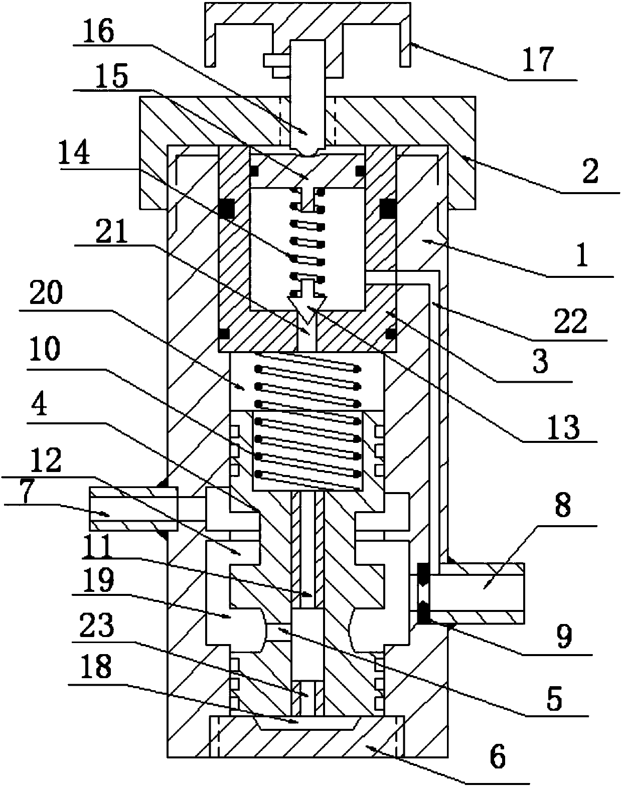
[0020] The specific embodiments of the present invention will be further described below in conjunction with the accompanying drawings:

[0021] like figure 1 As shown in the figure, a constant flow valve of the present invention includes a valve body 1, an upper valve seat 3, a valve core 4, a water inlet pipe 7 and a water outlet pipe 8; The upper locking nut 2 is locked and fixed, and the lower part of the valve body 1 is locked and fixed by the lower locking nut 6 at the bottom; In the main spring 10, a lower valve cavity 19 is set between the lower part of the valve core 4 and the lower part of the valve body, and a back pressure cavity 18 is set between the bottom of the valve core 4 and the lower locking nut 6; the water inlet pipe 7 and the water outlet pipe 8 are respectively arranged in the valve body On both sides of 1, the water inlet pipe 7 is connected to the water outlet pipe 8 through the lower valve chamber 19, and the valve body 1 in front of the water outle...


PUM


Abstract

The invention relates to a constant flow valve and a working method thereof. An upper valve seat is arranged on the upper portion of a valve body. The lower portion of the valve body is fixedly lockedthrough a lower locking nut at the bottom. A valve element is arranged in the middle of the valve body. The portion between the valve element and the upper valve seat is provided with an upper valvecavity and a main spring. A lower valve cavity is formed between the lower portion of the valve element and the lower portion of the valve body. A backpressure cavity is formed between the bottom of the valve element and the lower locking nut. A water outlet pipe and a water inlet pipe are arranged at the two sides of the vale body correspondingly. The water inlet pipe communicates with the wateroutlet pipe through the lower valve cavity. The upper valve cavity communicates with the upper valve seat through a channel (a). A conical pilot valve arranged in the upper valve seat abuts against one end of the channel (a). The upper valve seat communicates with the water outlet pipe through a channel (b). The interior of the valve element communicates with the lower valve cavity through a channel (d), communicates with the backpressure cavity through a channel (c) and communicates with the upper valve cavity through a damping hole. By means of the constant flow valve and the working methodthereof, the water yield of tap water can be precisely adjusted and controlled; fluctuation of the water pressure is overcome; the water yield is maintained to be constant; the constant flow valve issimple in structure and convenient to mount and use; and saving and rational utilization of water resources are promoted.

Description

technical field [0001] The invention relates to a valve, in particular to a constant flow valve and a working method thereof. Background technique [0002] The total amount of water resources on earth is about 1.38 billion cubic kilometers, of which 97.5% is seawater (1.345 billion cubic kilometers). Fresh water only accounts for 2.5%, most of which are polar ice and snow glaciers and groundwater, and only 0.01% is suitable for human enjoyment. In the 20th century, the world's population tripled, while human water use increased fivefold. Many countries around the world are facing a water crisis: 1.2 billion people suffer from water shortages, 3 billion lack water sanitation, and 3 to 4 million people die each year from water-related diseases. By 2025, the water crisis will spread to 48 countries and 3.5 billion people will be trapped by water. The deterioration of ecosystems and the destruction of biodiversity brought about by the water crisis will also seriously threaten...

Claims


Application Information

Patent Timeline
IPC IPC(8): F16K17/22
Inventor 董喜荣张智勇董铭欣
Owner ANGANG STEEL CO LTD
Why Eureka
Try Eureka