Refrigeration cycle device
A refrigeration cycle and refrigerant technology, applied in refrigerators, refrigeration components, refrigeration and liquefaction, etc., can solve the problems of complex cooling water circuit and achieve the effect of improving the efficiency of refrigeration cycle
- Summary
- Abstract
- Description
- Claims
- Application Information
AI Technical Summary
Problems solved by technology
Method used
Image

Examples
no. 1 approach
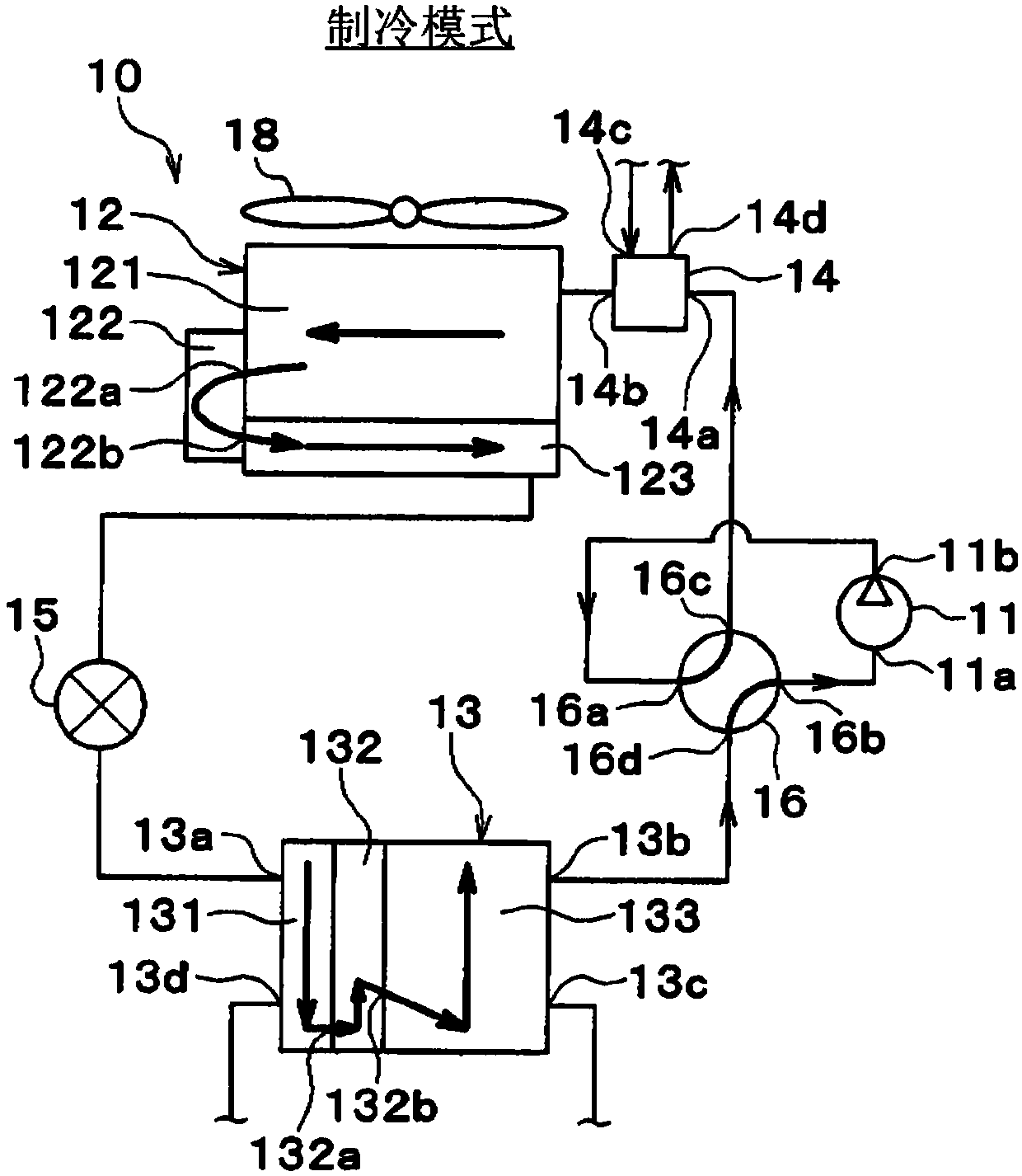
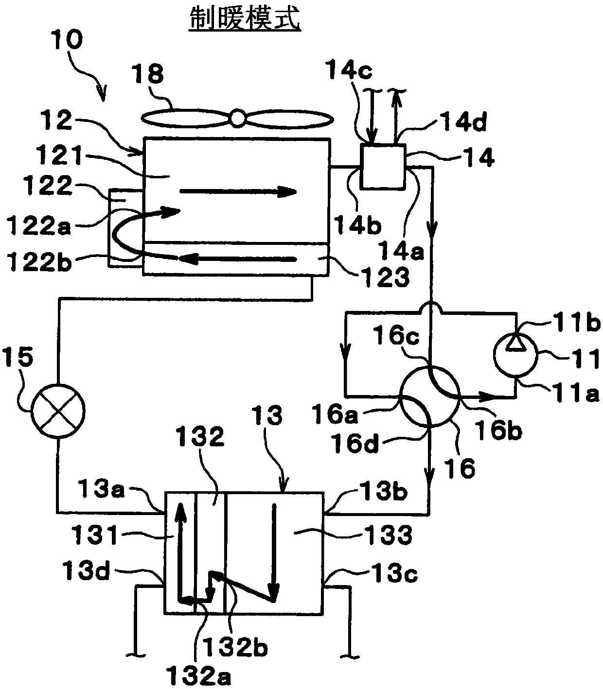
[0087] figure 1 The illustrated refrigeration cycle device 10 is used to adjust a vehicle interior space to an appropriate temperature. In the present embodiment, the refrigeration cycle device 10 is applied to a hybrid vehicle that obtains driving force for vehicle travel from an engine (internal combustion engine) and a travel electric motor.
[0088] The hybrid vehicle according to the present embodiment is configured as a plug-in hybrid vehicle capable of charging a battery (vehicle battery) mounted on the vehicle with electric power supplied from an external power supply (commercial power supply) while the vehicle is parked. As the battery, for example, a lithium ion battery can be used.
[0089] The driving force output from the engine is used not only for driving the vehicle but also for operating the generator. In addition, the electric power generated by the generator and the electric power supplied from the external power source can be stored in the battery, and th...
no. 2 approach
[0248] In the above-mentioned embodiment, the expansion valve 15 is a two-way expansion valve that can depressurize and expand the refrigerant even if the refrigerant flows back. One-way expansion valve for decompression and expansion.
[0249] Such as Figure 11 , Figure 12 As shown, the refrigeration cycle apparatus 10 includes a refrigerant flow switching valve 17 for an expansion valve. The refrigerant flow switching valve 17 for an expansion valve keeps the refrigerant flow direction relative to the expansion valve 15 always in the same direction regardless of the air-conditioning mode. The expansion valve refrigerant flow switching valve 17 is a decompression refrigerant flow switching device that makes the flow direction of the refrigerant in the expansion valve 15 as a decompression device the same in the cooling mode and the heating mode. The operation of the expansion valve refrigerant flow switching valve 17 is controlled by the control device 40 .
[0250] The...
no. 3 approach
[0257] In the above-mentioned second embodiment, the air-refrigerant heat exchanger 12 has the gas-liquid separation part 122, and the first cooling water-refrigerant heat exchanger 13 has the gas-liquid separation part 132, but in this embodiment, as Figure 13 , Figure 14 As shown, an accumulator 18 is provided instead of the gas-liquid separators 122 and 132 .
[0258] The accumulator 18 is disposed between the refrigerant outflow port 16 b of the refrigerant flow switching valve 16 and the refrigerant suction port 11 a of the compressor 11 .
[0259] Such as Figure 13 As shown, when the air conditioning mode is the cooling mode, the refrigerant flowing out of the first coolant-refrigerant heat exchanger 13 flows into the accumulator 18 . The gas-liquid of the refrigerant is separated in the accumulator 18 , the separated gas-phase refrigerant is sucked into the compressor 11 , and the separated liquid-phase refrigerant is stored in the accumulator 18 .
[0260] Such a...
PUM
 Abstract
Description
Claims
Application Information
 - R&D Engineer
- R&D Manager
- IP Professional
- Industry Leading Data Capabilities
- Powerful AI technology
- Patent DNA Extraction
Browse by: Latest US Patents, China's latest patents, Technical Efficacy Thesaurus, Application Domain, Technology Topic.
© 2024 PatSnap. All rights reserved.Legal|Privacy policy|Modern Slavery Act Transparency Statement|Sitemap