Apparatus capable of continuously rolling and breaking
A technology of rotating connection and roller, applied in the crushing device, can be used in the field of continuous rolling, and can solve the problems of cumbersome operation, high configuration and maintenance costs, low production efficiency, etc., and achieve the effect of high crushing efficiency
- Summary
- Abstract
- Description
- Claims
- Application Information
AI Technical Summary
Problems solved by technology
Method used
Image
Examples
specific Embodiment approach 1
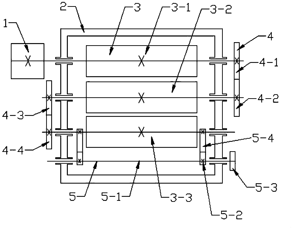
[0018] Combine below figure 1 , 2 , 3, 4, and 5 illustrate this embodiment. The present invention relates to the technical field of rolling tools, more specifically, a device capable of continuous rolling and crushing, including: a motor 1, a frame 2, a roller group 3, The transmission mechanism 4, the material can automatically and directly enter the next rolling and crushing from the first rolling and crushing, so as to efficiently complete multiple continuous rolling and crushing of the material, the rolling and crushing efficiency is high, and the material rolling, The final thickness and particle size of crushing can be adjusted, which enhances the controllability of material rolling and crushing.
[0019] Roller group 3 is made up of a plurality of rollers, and described a plurality of rollers are all rotatably connected on the frame 2, and transmission mechanism 4 is made up of a plurality of gears, and described a plurality of gears are respectively fixedly connected ...
specific Embodiment approach 2
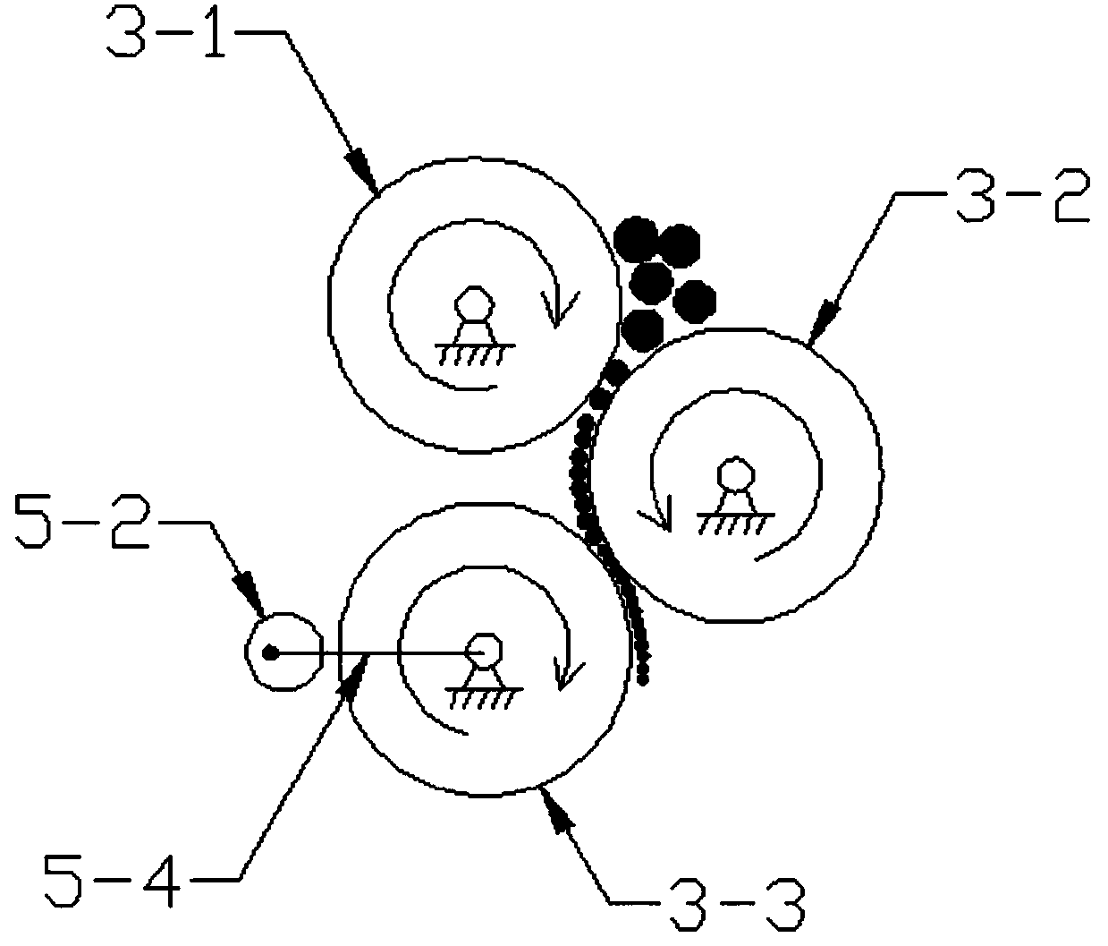
[0020] Combine below figure 1 , 2 Describe this embodiment, this embodiment will further explain Embodiment 1, the roller set 3 includes roller I3-1, roller II3-2 and roller III3-3, roller I3-1 is rotatably connected to the machine On the upper layer of frame 2, roller II 3-2 is rotatably connected to the middle layer of frame 2, roller III 3-3 is rotatably connected to the lower layer of frame 2, and the output shaft of motor 1 is fixedly connected to the left end of roller I 3-1; The above-mentioned transmission mechanism 4 includes gear I4-1, gear II4-2, gear III4-3 and gear IV4-4, gear I4-1 is fixedly connected to the right end of roller I3-1, gear II4-2 is fixedly connected to the roller The right end of Ⅱ3-2, gear Ⅲ4-3 is fixedly connected to the left end of roller Ⅱ3-2, gear Ⅳ4-4 is fixedly connected to the left end of roller Ⅲ3-3, and gear Ⅰ4-1 meshes with gear Ⅱ4-2, gear Ⅲ4 -3 meshes with gear IV 4-4. Motor 1 drives roller I3-1 and gear I4-1 to rotate, gear I4-1 dr...
specific Embodiment approach 3
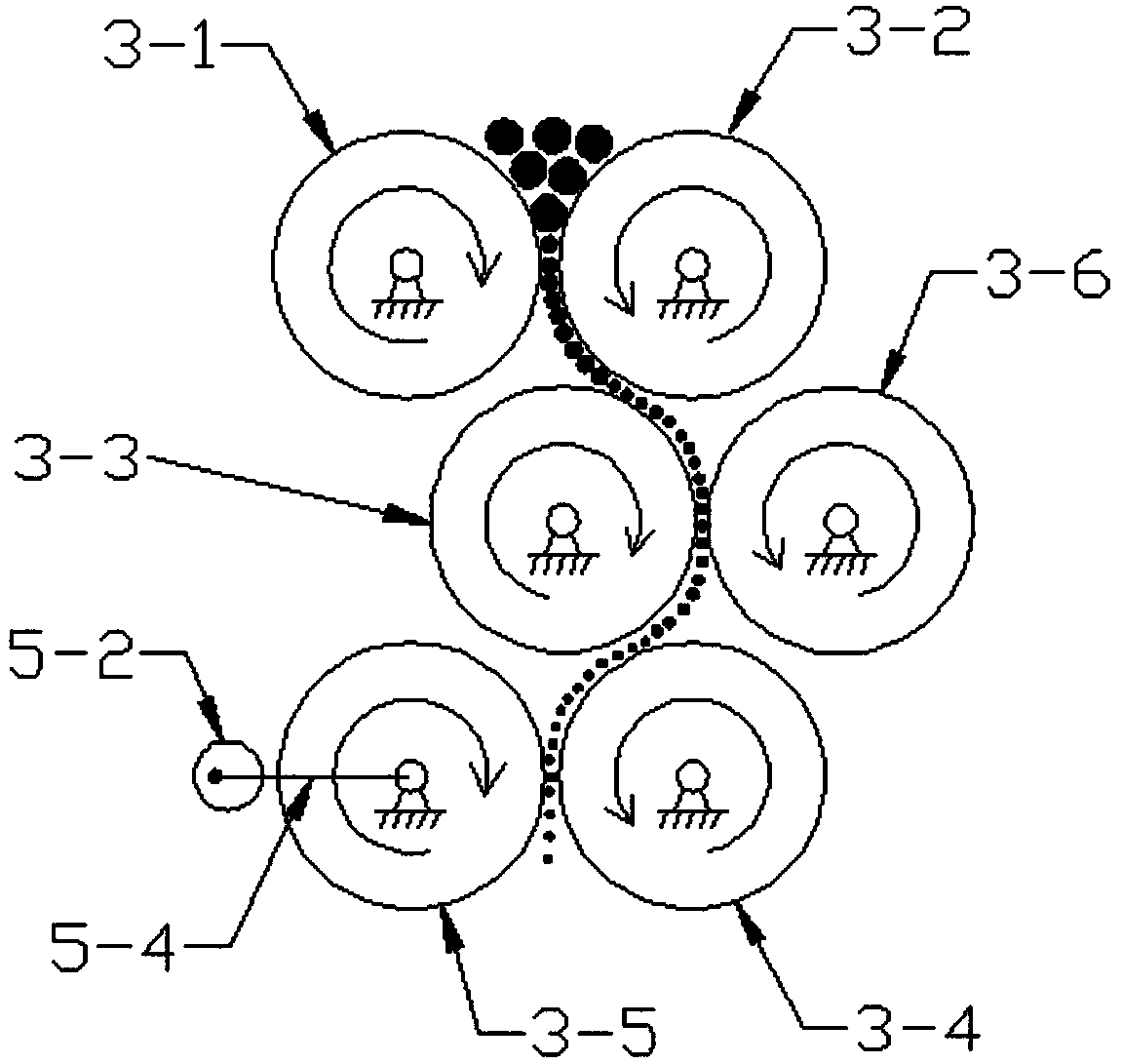
[0021] Combine below image 3 , 4 , 5 illustrate this embodiment, and this embodiment will further explain Embodiment 1. The roller set 3 includes roller I 3-1, roller II 3-2, roller III 3-3, roller IV 3-4, roller Roller Ⅴ3-5 and roller Ⅵ3-6, roller Ⅰ3-1 and roller Ⅱ3-2 are rotatably connected to the upper layer of frame 2, and roller Ⅲ3-3 and roller Ⅵ3-6 are rotatably connected to the middle layer of frame 2 , roller IV3-4 and roller V3-5 are rotatably connected to the lower layer of frame 2; the transmission mechanism 4 includes gear I4-1, gear II4-2, gear III4-3, gear IV4-4, gear V4 -5. Gear Ⅵ4-6, gear Ⅶ4-7, gear Ⅷ4-8 and gear Ⅸ4-9, gear Ⅰ4-1 is fixedly connected to the right end of roller Ⅰ3-1, gear Ⅱ4-2 is fixedly connected to roller Ⅱ3-2 The right end of the gear III4-3 is fixedly connected to the left end of the roller II3-2, the gear IV4-4 is fixedly connected to the left end of the roller III3-3, the gear V4-5 is fixedly connected to the right end of the roller III3...
PUM
 Abstract
Description
Claims
Application Information
 - R&D
- Intellectual Property
- Life Sciences
- Materials
- Tech Scout
- Unparalleled Data Quality
- Higher Quality Content
- 60% Fewer Hallucinations
Browse by: Latest US Patents, China's latest patents, Technical Efficacy Thesaurus, Application Domain, Technology Topic, Popular Technical Reports.
© 2025 PatSnap. All rights reserved.Legal|Privacy policy|Modern Slavery Act Transparency Statement|Sitemap|About US| Contact US: help@patsnap.com


