Non-contact tool setting gauge

A non-contact, tool setting technology, used in metal processing mechanical parts, measuring/indicating equipment, metal processing equipment, etc., can solve problems such as production and processing effects, probe wear function, and long working time.

Inactive Publication Date: 2018-01-30
YANGZHOU HENGDE IND TECH CO LTD
View PDF1 Cites 0 Cited by
  • Summary
  • Abstract
  • Description
  • Claims
  • Application Information

AI Technical Summary

Problems solved by technology

It is generally divided into two types: contact type and non-contact type. The contact type has the problems of probe wear and single function, while the non-contact type is widely accepted because it does not have such problems.
However, the current non-contact tool setting instrument still has the following problems: because it only measures a beam of light, in order to accurately measure the length, diameter, and da...

Method used


Image

  • Non-contact tool setting gauge
  • Non-contact tool setting gauge
  • Non-contact tool setting gauge

Examples


Embodiment Construction

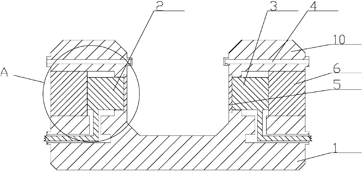
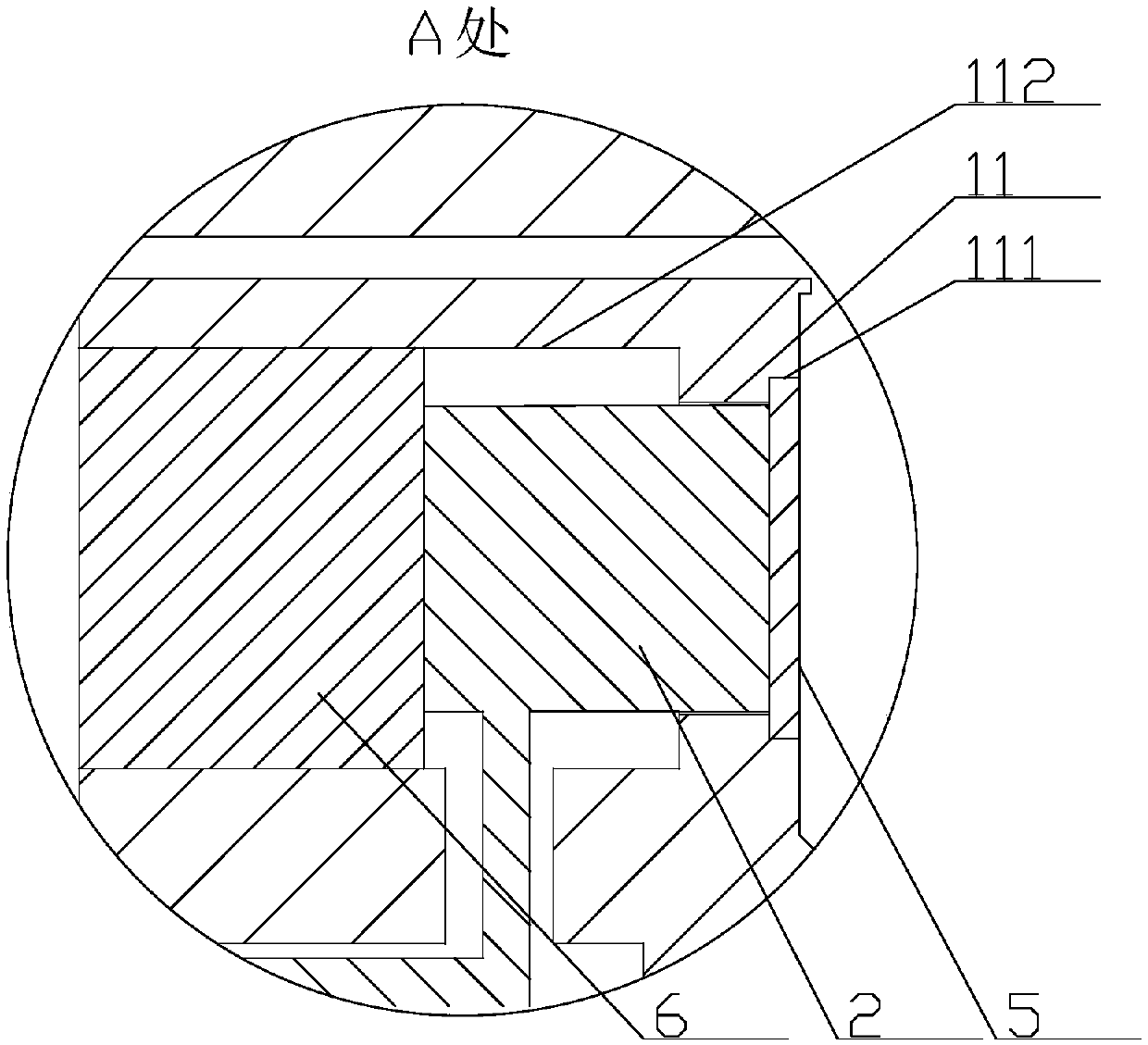
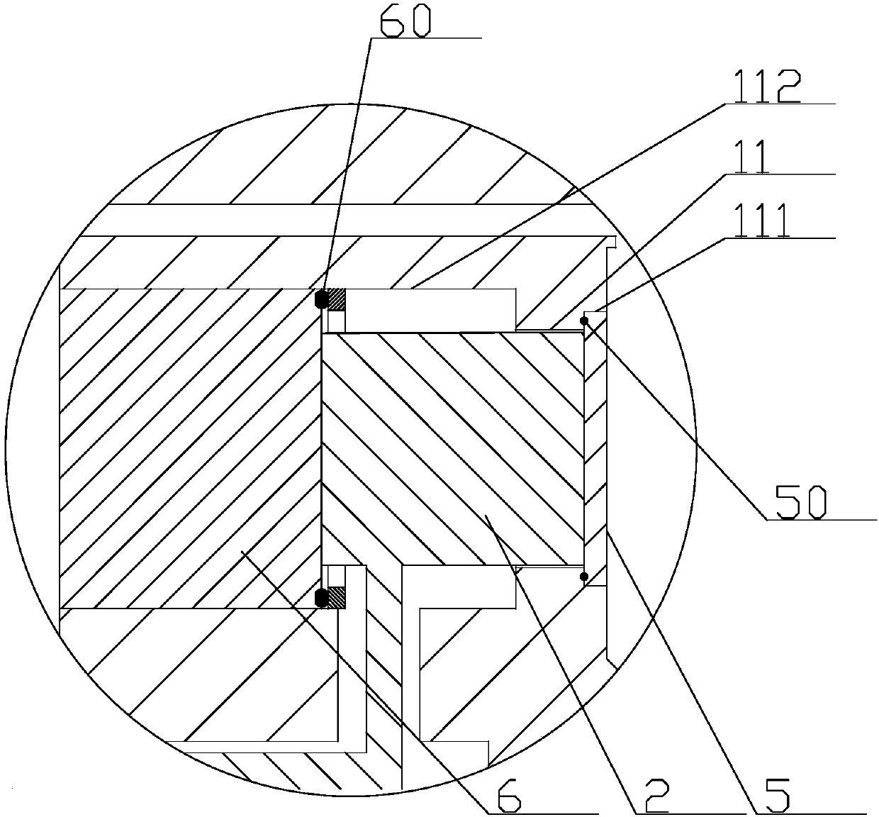
[0022] The present invention as Figure 1-4 As shown, it includes a seat body 1, a laser transmitter 2, a laser receiver 3 and an air blowing assembly 4. The seat body 1 has a pair of mounting seats 10 arranged symmetrically along the center, and the upper part of the mounting seat 10 is provided with Accommodating holes 11, the two accommodating holes 11 are concentric and are respectively used to accommodate the laser transmitter 2 and the laser receiver 3 which are arranged oppositely;

[0023] The tool setting instrument also includes a pair of high-strength lenses 5 and a pair of mounting blocks 6, the high-strength lenses 5 are fixedly connected to the opening of the accommodating hole 11 toward the center of the seat body 1, and the mounting blocks 6 are fixedly connected At the opening of the accommodating hole 11 away from the center of the base body 1, the laser emitter or laser receiver is clamped between the high-strength lens and the mounting block. In this case,...


PUM


Abstract

The invention provides a non-contact tool setting gauge and relates to the field of tool measurement devices, in particular to the automatic improvement on tool gauges in numerically-controlled machine tools. The on-contact tool setting gauge is ingenious in structure, good in use effect, long in service life and excellent in stability. The tool setting gauge further comprises a pair of high-strength lenses and a pair of installation blocks, each high-strength lens is fixedly connected to the position, facing the center of a base body, of an orifice of a containing hole, and each installationblock is fixedly connected to the position, away from the center of the corresponding base body, of the orifice of the corresponding containing hole. Sealing connection is kept between the high-strength lenses and the containing holes, and sealing connection is kept between the installation blocks and the containing holes. A first sinking table is arranged at the position, facing the center of thecorresponding base body, of the orifice of each containing hole, and each high-strength lens is fixedly connected with the inside of the corresponding first sinking table; a second sinking table is arranged at the position, away from the center of the corresponding base body, of the orifice of each containing hole, and each installation block is detachably connected with the inside of the corresponding second sinking table. The non-contact tool setting gauge has the advantages of being ingenious in structure, good in use effect, long in service life and excellent in stability.

Description

technical field [0001] The invention relates to the field of tool measuring equipment, in particular to the improvement of an automatic tool setting instrument in a numerically controlled machine tool. Background technique [0002] With the popularity of CNC machine tools and the advancement of automated production requirements, the use of online tool setting instruments for machine tools is becoming more and more extensive. It is generally divided into two types: contact type and non-contact type. The contact type has the problem of probe wear and single function, while the non-contact type is widely accepted because it does not have such problems. However, the current non-contact tool setting instrument still has the following problems: because it only measures a beam of light, in order to accurately measure the length, diameter, and damage of the tool, the tool must be repeatedly placed in the tool setting instrument. It takes a lot of working time to feed, flip, and rot...

Claims


Application Information

Patent Timeline
IPC IPC(8): B23Q17/24
Inventor 卞正文王利平宰广平佘佳陆坤靓
Owner YANGZHOU HENGDE IND TECH CO LTD
Why Eureka
Try Eureka