
Robot wrist joint mechanism driven by omnidirectional wheels

A robot wrist and omni-directional wheel technology, applied in the direction of manipulators, manufacturing tools, joints, etc., can solve the problems of large volume, complex structure, large vibration and noise, etc., and achieve the effect of smooth movement, flexible steering, and small size

Pending Publication Date: 2018-01-30
GUILIN UNIV OF ELECTRONIC TECH
View PDF9 Cites 3 Cited by
  • Summary
  • Abstract
  • Description
  • Claims
  • Application Information

AI Technical Summary

Problems solved by technology

[0004] The existing three-degree-of-freedom robot wrist joints usually have disadvantages and deficiencies such as complex structure, large volume, and large vibration and noise during work due to reasons such as drive and transmission.

Method used


Image

  • Robot wrist joint mechanism driven by omnidirectional wheels
  • Robot wrist joint mechanism driven by omnidirectional wheels
  • Robot wrist joint mechanism driven by omnidirectional wheels

Examples


Embodiment Construction

[0017] The technical solutions of the present invention will be further described below in conjunction with the embodiments shown in the accompanying drawings.

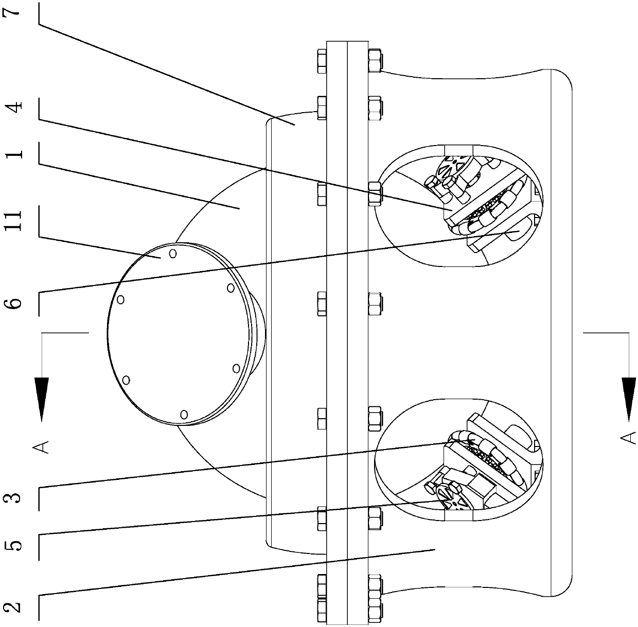
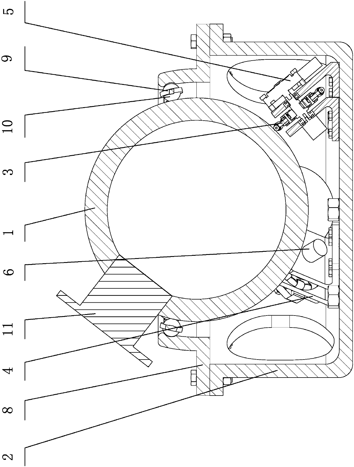
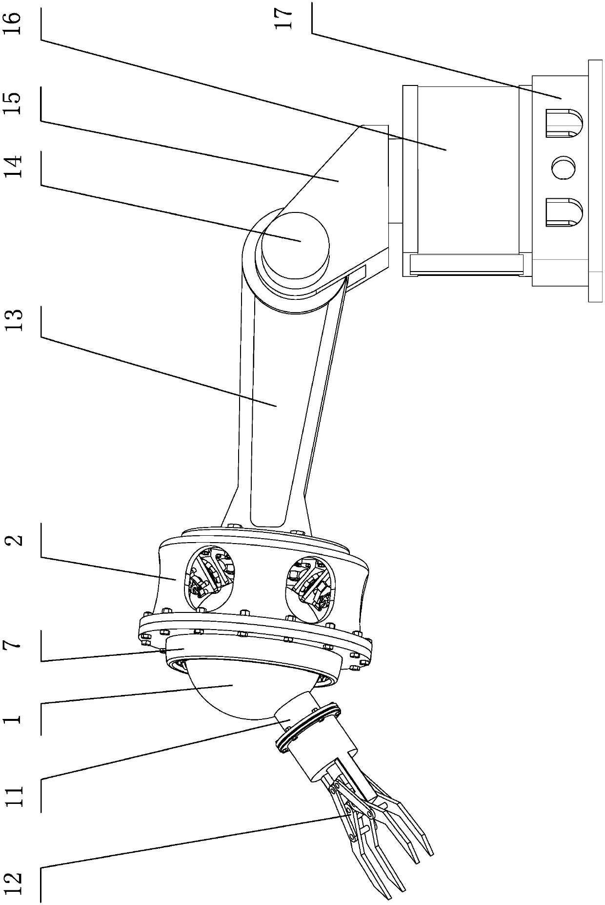
[0018] The omnidirectional wheel-driven robot wrist joint mechanism of the present invention includes a ball joint 1, a ball joint cup frame 2 and a single row of omnidirectional wheels 3, the lower hemisphere of the ball joint 1 is centered in the ball joint cup frame 2, Three single-row omnidirectional wheels 3 are evenly distributed on the inner circumference of the ball joint cup frame 2 and are in frictional contact with the lower hemisphere of the ball joint 1, and the three single-row omnidirectional wheels 3 pass through the corresponding wheel frame 4 (installed on the ball joint Cup frame 2) is installed and the centerlines of rotation of three single-row omnidirectional wheels 4 are obliquely downward and intersect at one point. The ball joint motor 5 of the single-row omnidirectional wheel 3 and the encode...


PUM


Abstract

The invention discloses a robot wrist joint mechanism driven by omnidirectional wheels. The robot wrist joint mechanism comprises a ball joint and is characterized in that the lower half ball of the ball joint is arranged in a ball joint cup-shaped rack and is friction contact three single-row omnidirectional wheels evenly distributed on the inner periphery of the ball joint cup-shaped rack, the three single-row omnidirectional wheels are mounted through corresponding wheel racks, the rotation central lines of the three single-row omnidirectional wheels inclines downwards and intersect at onepoint, the intersection point is locate right below the ball center of the ball joint, each wheel rack is provided with a ball joint motor for driving the corresponding single-row omnidirectional wheel and an encoder for detecting the corresponding single-row omnidirectional wheel, the ball joint cup-shaped rack is provided with a disconnection preventing component acting on the upper half ball ofthe ball joint, and the upper half ball of the ball joint is provided with a platform seat allowing an operation tool to be mounted. The robot wrist joint mechanism has the advantages that the positions and postures of mechanical tongs in a three-dimensional space can be regulated and changed, and the robot wrist joint mechanism is stable in motion, flexible in steering and small and exquisite insize.

Description

technical field [0001] The invention relates to a robot joint structure, in particular to a robot wrist joint mechanism driven by omnidirectional wheels. Background technique [0002] An industrial robot is a multi-joint manipulator or a multi-degree-of-freedom automation device for the industrial field. It can imitate certain movement functions of the human hand and arm to grasp, carry objects or operate tools according to the original program. The wrist joint is an important part of the connection between the arm of the robot and the mechanical gripper. Its main function is to adjust and change the position and posture of the mechanical gripper in three-dimensional space. Therefore, the flexibility and The range of motion in space directly affects the overall function and performance of the robot at work. [0003] At present, robot wrist joints are divided into two degrees of freedom and three degrees of freedom, and there are mainly two driving forms: gear set drive and ...

Claims


Application Information

Patent Timeline
Patent Type & Authority Applications(China)
IPC IPC(8): B25J17/00
Inventor 黄用华孙兵庄未钟艳如黄美发匡兵孙永厚刘夫云钟永全
Owner GUILIN UNIV OF ELECTRONIC TECH
Learn More