[0021] In order to make the objectives, technical solutions and advantages of the present invention clearer, the present invention will be further described in detail below with reference to the accompanying drawings. It should be understood that the specific embodiments described herein are only used to explain the present invention, but not to limit the present invention.
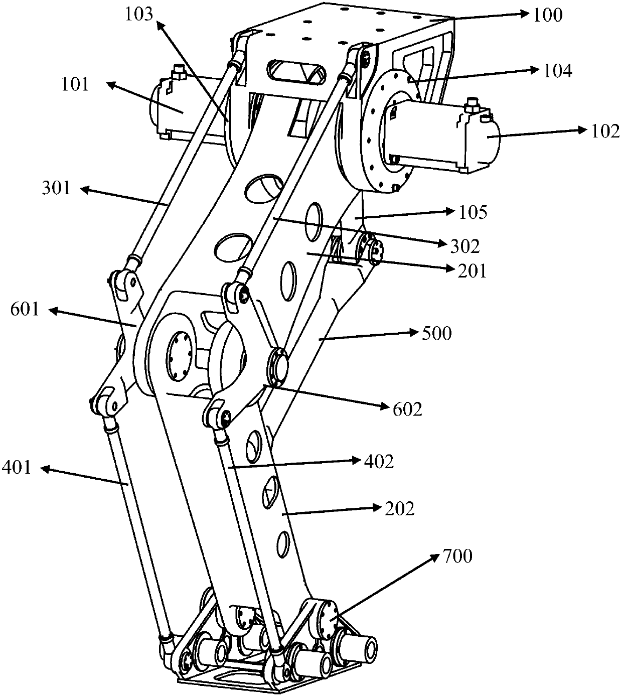
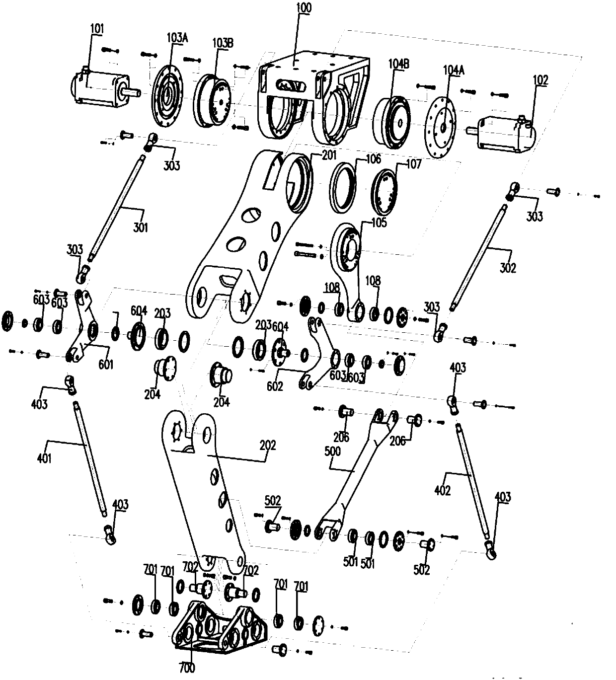
[0022] According to an embodiment of the present invention, such as figure 1 As shown, a top-mounted two-axis automatic blanking robot includes: base 100, servo motor 101, servo motor 102, transmission device 103, transmission device 104, crank 105, mechanical arm I201, mechanical arm II202, and upper link 301 And 302, lower links 401 and 402, transmission link 500, corners 601 and 602, and clamp mounting head 700. The motor 101 is fixedly installed on the transmission device 103, the transmission device 103 is fixedly installed on the left side of the base 100, the motor 102 is fixedly installed on the transmission device 104, and the transmission device 104 is fixedly installed on the right side of the base 100. The crank 105 is installed inside the upper end of the robotic arm I201. The upper end of the crank 105 is connected with the transmission device 104, and the lower end is movably connected with the transmission connecting rod 500. The crank 105 can be driven by the transmission device 104 to drive the transmission connecting rod 500 for reciprocating motion under the drive of the motor 102 . The upper end of the robotic arm I201 is movably connected with the base 100, and is connected with the transmission device 103, which can be rotated by the movable connection part of the lower edge of the motor 101 and the base 100 through the transmission device 103; the lower end of the mechanical arm I201 and the mechanical arm II202 The upper end is movably connected, which can drive the mechanical arm II202 to move. The connecting ends of the robot arm I201 and the robot arm II202 are two externally extending connecting supports, and the two supports are connected by a movable connection to connect the robot arm I201 and the robot arm II202 together. The corner corners 601 and 602 are respectively installed on the two outer sides of the connecting part of the robot arm I201 and the robot arm II202 and movably connected with the connecting part of the robot arm I201 and the robot arm II202. The upper end of the mechanical arm II202 is movably connected with the mechanical arm I201, and the lower end is movably connected with the clamp mounting head 700. One end of the transmission connecting rod 500 is movably connected with the crank 105, and the other end is movably connected with the mechanical arm II202. The transmission connecting rod 500 can drive the mechanical arm II202 to move back and forth under the drive of the crank 105. The lower end of the upper link 301 is movably connected with the corner 601, and the top end is movably connected with the top left side of the base 100; the lower end of the upper link 302 is movably connected with the jog 602, and the top end is movably connected with the top right of the base 100. The top end of the lower connecting rod 401 is movably connected to the corner corner 601, and the lower end is movably connected to the bottom end of the left side wall of the fixture mounting head 700; the top end of the lower connecting rod 402 is movably connected to the corner corner 602, and the lower end is movably connected to the bottom of the right side wall of the fixture mounting head 700 End active connection. The clamp mounting head 700 is a hollow structure, and both sides are triangular-like structures. The connecting part of the robot arm II202 and the fixture mounting head 700 is two extended connecting supports. The connecting support of the robot arm II202 is movably connected with the top side of the fixture mounting head 700, and the lower connecting rods 401 and 402 are connected to the fixture mounting head. The bottom ends of one side of 700 are movably connected. The clamp mounting head 700 can follow the movement of the robot arm II202 under the joint action of the robot arm II202 and the lower links 401 and 402, and the bottom surface always points to the vertical direction.
[0023] According to an embodiment of the present invention, the servo motor 101 and the servo motor 102 use 4.4 KW servo motors.
[0024] According to an embodiment of the present invention, two sets of rotating devices can be selected, and each set of transmission devices corresponds to at least two motors, and multiple motors jointly provide power for the transmission device.
[0025] According to an embodiment of the present invention, such as figure 2 As shown, the transmission device 103 includes a fixing device 103A and a reducer 103B. The servo motor 101 is fixedly installed on the fixing device 103A, the output shaft is connected to the input shaft of the reducer 103B, and the fixing device 103A fixes the reducer 103B to the base 100. On the left side wall. The transmission device 104 includes a fixing device 104A and a reducer 104B. The servo motor 102 is fixedly installed on the fixing device 104A. The output shaft is connected to the input shaft of the reducer 104B. The fixing device 104A fixes the reducer 104B to the right side wall of the base 100 on. A slot is provided in the center of one end of the robotic arm I201, and the top of the crank 105 is installed in the slot through a cross roller bearing 106. The slot divides the end of the robotic arm I201 into left and right sides, one of which is directly fixedly connected to the reducer 103B; the other side is provided with a through groove, and a cross roller bearing 106 is fixedly installed in the through groove. One end of the inner ring of the cross roller bearing 106 located inside the robot arm I201 is fixedly connected to the top end of the crank 105, and the other end is fixedly connected to the flange 107. The flange 107 is fixed to the inner ring of the cross roller bearing 106 at one end, and fixedly connected to the reducer 104B at the other end. The robot arm I201 is installed at the bottom of the base 100 through the reducer 103B, the reducer 104B, the flange 107, and the cross-roller bearing 106, and can be driven by the reducer 103B to rotate along the rotation axis of the reducer 103B. The bottom end of the crank 105 is provided with a shaft hole, and two tapered roller bearings 108 are installed in the shaft hole. Both ends of the transmission connecting rod 500 are each provided with two connecting supports. The connecting supports are provided with shaft holes. The rotating shaft 206 passes through the shaft hole of the connecting support at one end of the transmission connecting rod 500 and the tapered roller bearing at the bottom end of the crank 105 The inner ring of 108 is connected to the crank 105. The connecting ends of the robot arm I201 and the robot arm II202 are two extended connecting supports respectively. The tapered roller bearings 203 are fixedly installed in the two connecting supports of the robot arm I201, and the robot arm I201 and the robot arm are connected through a shaft 204 Two connecting supports for II202. The corner corners 601 and 602 are respectively installed on the two outer sides of the connecting part of the robot arm I201 and the robot arm II202. The corner ends are each provided with a through hole, and two tapered roller bearings 603 are fixedly installed in the through hole. Pass through the inner ring of the tapered roller bearing 603 inside the corners 601 and 602 and the support shaft hole of the robot arm I201, and connect the corners 601 and 602 to the outside of the support of the robot arm I201. The lower end of the upper link 301 and the joggle 601 are hingedly connected by a rod end joint bearing 303, and the top end is hingedly connected with the top left side of the base 100 by a rod end joint bearing 303; the lower end of the upper link 302 and the jog 602 are hingedly connected by a rod end joint The bearing 303 is hingedly connected, and the top end is hingedly connected to the top right side of the base 100 through a rod end joint bearing 303. The top end of the lower connecting rod 401 is hingedly connected with the jog 601 through a rod end joint bearing 403, and the lower end is hingedly connected with the bottom end of the left side wall of the fixture mounting head 700 through a rod end joint bearing 403; the top end of the lower connecting rod 402 passes through the jog 602 The rod end joint bearing 403 is hingedly connected, and the lower end is hingedly connected to the bottom end of the right side wall of the fixture mounting head 700 through the rod end joint bearing 403. There are 3 pairs of openings on both sides of the robot arm II202 near the end of the transmission connecting rod 500, one of which is equipped with a tapered roller bearing 501, the rotating shaft 502 passes through the inner ring of the tapered roller bearing 501 and the transmission The connecting support shaft hole of the connecting rod 500 connects the mechanical arm II202 and the transmission connecting rod 500 together. The clamp mounting head 700 has a hollow structure, and both sides are triangular-like structures. The top and low ends of both sides are provided with openings, and two tapered roller bearings 701 are fixedly installed in the top opening. The connecting part of the robot arm II202 and the fixture mounting head 700 is two extended connecting supports, and the two rotating shafts 702 respectively pass through the inner ring of the tapered roller bearing 701 at the top of the two sides of the fixture mounting head 700 to connect the robot arm II202 Support connection. The openings at the bottom ends of the two side surfaces of the clamp mounting head 700 are hinged with the connecting rods 401 and 402 through rod end joint bearings 403.
[0026] The working process of the present invention is: the base 100 is fixedly mounted on a rotatable turntable, and the servo motor 102 on the side of the base 100 drives the mechanical arm II202 through the crank 105 and the transmission connecting rod 500 to realize the left and right movement of the fixture mounting head 700; The robot arm I201 is driven by the servo motor 101 on the other side of the base 100 to realize the up and down movement of the robot, and the base 100 and the fixture mounting head 700 are connected through the corner turn 600 and the upper link 300 and the lower link 400. Under the control of the external control system, the robot can realize the arbitrary movement of the fixture mounting head 700 within the reach of the arm range through the lower link 300 and the mechanical arm II202 and keep the fixture mounting head 700 in a horizontal position. Install the fixture to realize the automatic blanking function.
[0027] The advantages of the present invention are that compared with the existing blank stacking machine, the top-mounted two-axis automatic blank stacking robot of the present invention not only has low noise, low mechanical vibration, and low maintenance cost, and has higher working efficiency.
[0028] It should be noted and understood that various modifications and improvements can be made to the invention described in detail above without departing from the spirit and scope of the claims of the invention. Therefore, the scope of the claimed technical solution is not limited by any specific exemplary teaching given.