Data transmission protection method and apparatus thereof

A data transmission and protection device technology, applied in wireless communication, electrical components, etc., can solve problems such as low efficiency, inability to protect multicast data, and excessive protection.

Active Publication Date: 2018-01-30
ZTE CORP
View PDF4 Cites 8 Cited by
  • Summary
  • Abstract
  • Description
  • Claims
  • Application Information

AI Technical Summary

Problems solved by technology

[0003] There are still some problems to be solved in the above RTS / CTS protection mechanism. The multicast data cannot be protected. The multicast data refers to the frame whose receiving address is set to the multicast address. The multicast address includes the broadcast address and the multicast address.
In addition, transmission protection is also used in parallel multi-user data transmission. In this scenario, traditional RTS / CTS can only perform RTS / CTS interaction with multiple users serially, which is very inefficient.
Multi-user transmission refers to the use of multiple frequency domain / air domain resources to transmit multiple data in parallel to multiple sites, although the new multi-user request to send frame (MU-RTS, multi-user RTS) can be used to allow multiple sites to send CTS at the same time Frames, these CTSs sent at the same time have exactly the same content format on the same channel, and the superimposed signals received by the AP for multiple users, but in the prior art, specific multiple stations need to be specified in advance in the MU-RTS frame to perform Response, in this way, although the AP can determine who sends the CTS, the AP often does not know which stations need transmission protection. That is, even if the station needs to send the CTS, it cannot send it without being instructed. Conversely, the station does not need it. CTS is sent, but CTS must be sent as long as it is instructed, and this method is equivalent to aggregating multiple RTSs into one frame, increasing the length of the protection frame, and using the new wireless frame MU-RTS, which is not conducive to backward compatibility. The old device (legacy device) cannot recognize the type of the frame. In addition, if the AP sends CTS to all stations participating in the communication in MU-RTS, it is easy to cause over-protection, which is not conducive to the improvement of network efficiency.
[0004] To sum up, in order to improve network efficiency, virtual carrier detection is still a basic technology used in WLAN, but for multicast data and multi-user transmission, new protection methods need to be designed to ensure the reliability of multicast data and multi-user transmission transmission, unfortunately, there is currently no relevant technology for reference

Method used


Image

  • Data transmission protection method and apparatus thereof
  • Data transmission protection method and apparatus thereof
  • Data transmission protection method and apparatus thereof

Examples


Embodiment 1

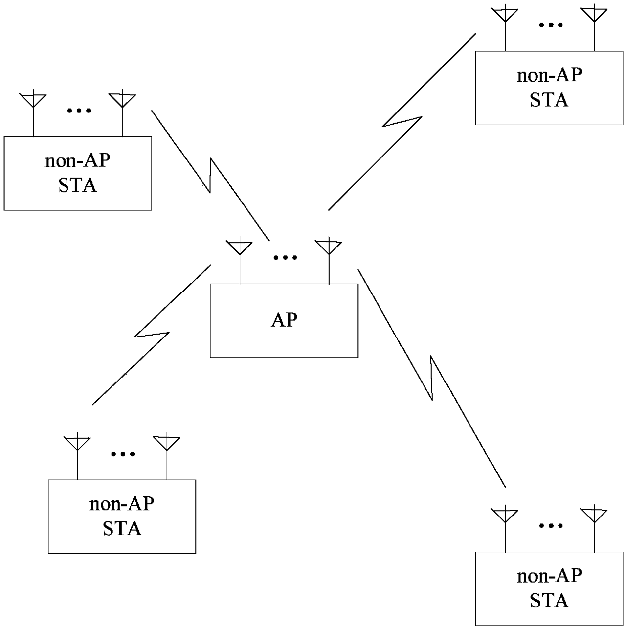
[0186] The AP and multiple stations STA1~STA10 form a BSS. The AP establishes a multicast service 1 with STA1~STA8, and assigns a multicast MAC address to identify the multicast service. The multicast MAC address and the unicast MAC address ( For example, the main difference between the MAC addresses of STA1 to STA10 is that the multicast address sets the I / G bit of the address to 1, and the unicast address sets this bit to 0. For example, in the 802.11 standard, the MAC address of 48 bits (B0 to B47) The B40 is the I / G bit. As an implementation manner, the multicast service may also be identified by other bits of the MAC address.

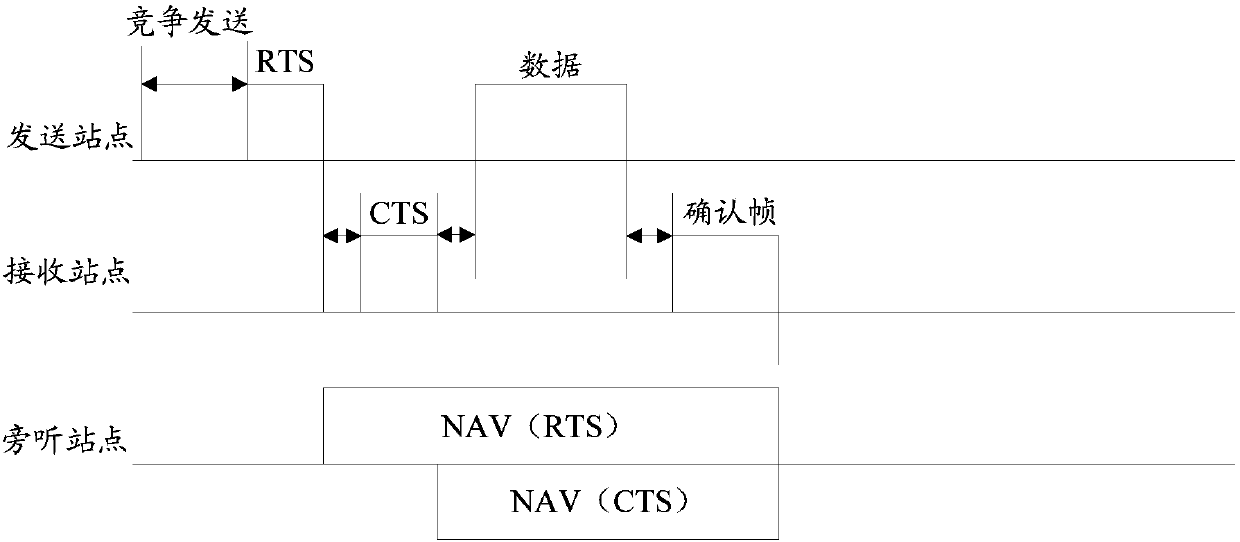
[0187] The AP gets the sending opportunity to send multicast data, such as Figure 5 As shown, in order to protect the multicast data to be sent, the AP performs RTS / CTS interaction before sending the multicast data. Different from the traditional RTS / CTS interaction, the AP sends an RTS frame whose receiving address is set to the multicast addres...

Embodiment 2

[0195] This embodiment describes different response factors and the case of judging whether the CTS can be sent. Similar to the first embodiment, the AP and multiple stations STA1-STA10 form a BSS, the AP and STA1-STA8 establish a multicast service, and assign a group The multicast MAC address is used to identify the multicast service.

[0196] The AP sends an RTS frame whose receiving address is set to the multicast address. The multicast address is the multicast address corresponding to the multicast service negotiated with STA1 to STA8 in advance, and the corresponding I / G bit is set to 1, indicating that the receiving address is multicast. address, STA1 finds that it belongs to the receiver of the multicast service, then STA1 is a station that may need to respond, but whether to respond needs further judgment, STA1 generates the probability P of sending CTS, and the probability P can be related to many factors. For example, it can be inversely proportional to the energy of...

Embodiment 3

[0205] This embodiment describes different response factors and the case of judging whether the CTS can be sent. Similar to the first embodiment, the AP and multiple stations STA1-STA10 form a BSS, the AP and STA1-STA8 establish a multicast service, and assign a group The multicast MAC address is used to identify the multicast service.

[0206] Suppose that the multicast data receiver uses the random backoff mechanism to decide whether to send CTS. Specifically, the station generates a random number a, where a is a non-negative integer that obeys the uniform distribution of [0, CW]. Each received address is a group In the RTS frame of the multicast service associated with itself, the random number a is subtracted by 1 or n, and if a becomes 0, the CTS can be sent, and the CW is the contention window. Specifically, as follows:

[0207] The AP sends an RTS frame whose receiving address is set to the multicast address. The multicast address is the multicast address corresponding...


PUM


Abstract

The invention discloses a data transmission protection method and an apparatus thereof. The method comprises the following steps that an initiator sends request sending information to a plurality of responders, and one or more response control information modules are arranged in the request sending information; the response control information modules are set to be the following two formats: a group format and a terminal format; the group format includes a group identification representing the plurality of responders; the terminal format includes a terminal identification representing the responders; and the initiator receives allowable sending information sent by the plurality of responders.

Description

technical field [0001] The present invention relates to data transmission protection technology, in particular to a data transmission protection method and device. Background technique [0002] like figure 1 As shown, a basic service set (BSS, basic service set) of a wireless local area network (WLAN, Wireless Local Area Network) generally includes an access point (AP, Access Point) and a plurality of non-AP stations (non-APstation). At present, shared media wireless networks, especially WLAN, in order to share the transmission medium between multiple sites or multiple networks and avoid mutual interference, generally use the carrier detection technology to determine whether the channel is occupied. The carrier detection technology can be divided into two types: physical Carrier Detect and Virtual Carrier Detect. Physical carrier detection refers to monitoring the wireless channel to determine whether the received energy exceeds a certain threshold, and if it exceeds the t...

Claims


Application Information

Patent Timeline
IPC IPC(8): H04W74/08
Inventor 邢卫民吕开颖韩志强
Owner ZTE CORP
Why Eureka
Try Eureka