Pipe bending mold, pipe bending machine and pipe bending method

A pipe bending machine and pipe bending technology, which is applied in the direction of forming tools, manufacturing tools, heat exchange equipment, etc., can solve the problems of waste of materials, low efficiency of pipe bending, time-consuming and laborious, etc., to save time and cost of pipe bending, and save materials , Ease of use

Active Publication Date: 2018-02-02
成都实好电器有限公司
View PDF8 Cites 5 Cited by
  • Summary
  • Abstract
  • Description
  • Claims
  • Application Information

AI Technical Summary

Problems solved by technology

[0004] Based on the above technical problems, the present invention provides a pipe bending die, which can realize the bending of multiple U-shaped p

Method used


Image

  • Pipe bending mold, pipe bending machine and pipe bending method
  • Pipe bending mold, pipe bending machine and pipe bending method
  • Pipe bending mold, pipe bending machine and pipe bending method

Examples


Embodiment

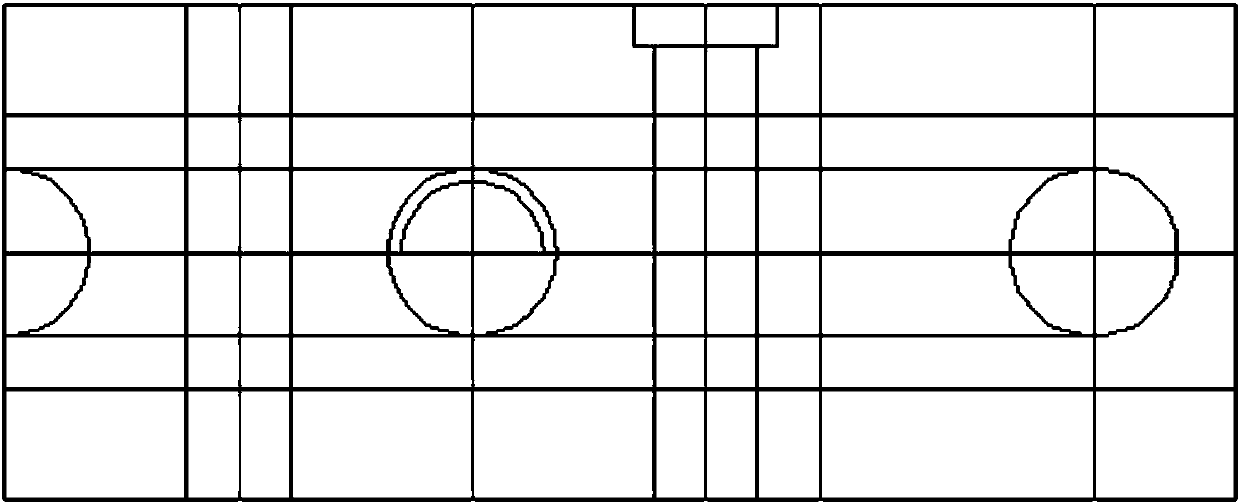
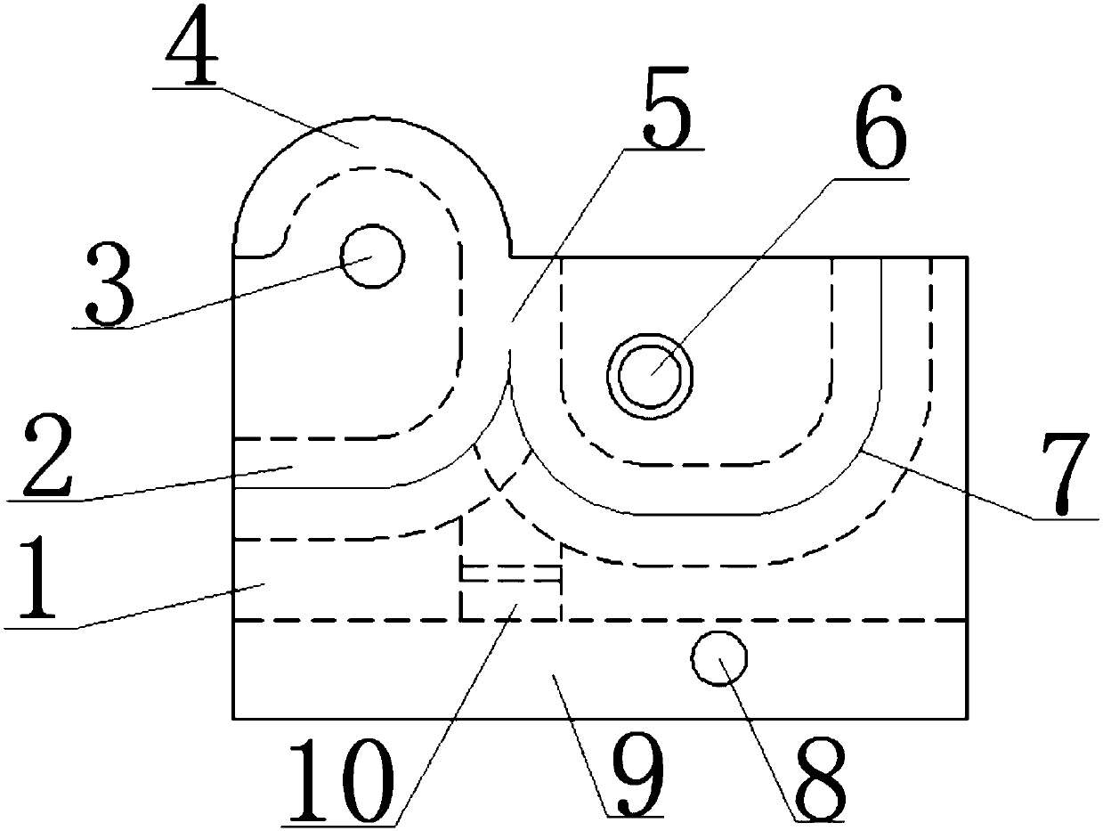
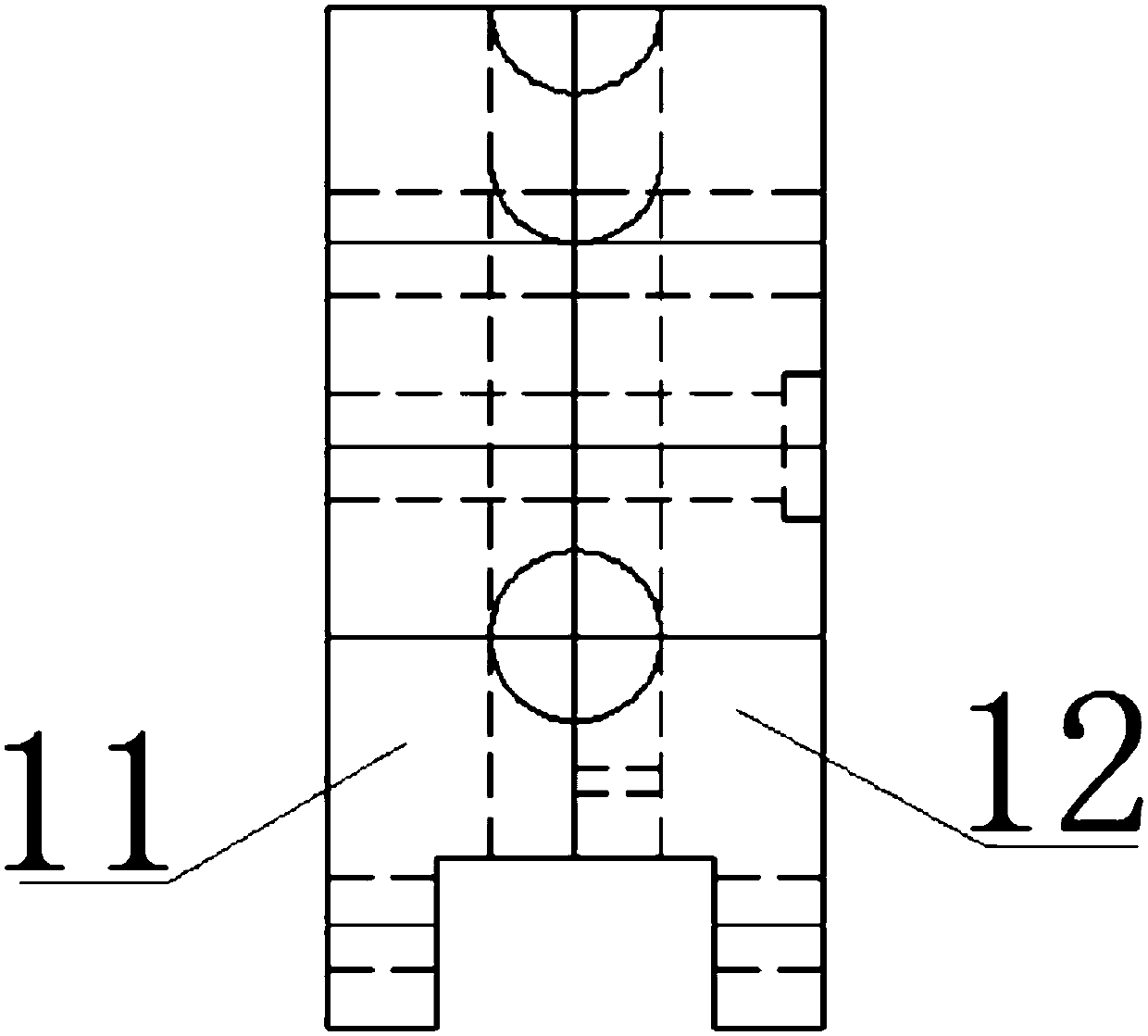
[0040] Such as Figure 1-Figure 3 Shown, a kind of pipe bending mold comprises the upper mold 12 and the lower mold 11 of identical structure and paired up and down;

[0041] The upper mold 12 or the lower mold 11 includes a main body 1, the upper end surface of the main body 1 is concavely formed with an L-shaped elbow cavity 2 and a U-shaped elbow cavity 7, and the bend of the L-shaped elbow cavity 2 and the U-shaped elbow cavity 7 The folds are all arc-shaped, and the L-shaped elbow cavity 2 and the U-shaped elbow cavity 7 are partially overlapped to form a shared elbow cavity 5. The two open ends of the U-shaped elbow cavity 7 are located on the front end of the main body 1. The open end of the shared elbow chamber 5 is any one of the two open ends of the U-shaped elbow chamber 7, one of the open ends of the L-shaped elbow chamber 2 is a shared elbow chamber 5, and the L The other opening end of the curved pipe cavity 2 is located on the left side of the main body 1, and ...


PUM


Abstract

The invention relates to a pipe bending mold. The pipe bending mold comprises an upper mold and a lower mold which have the same structure and are matched up and down; the upper mold or the lower moldcomprises a main body, an L-shaped pipe bending cavity and a U-shaped pipe bending cavity are formed in the upper end face of the main body in an inward sinking mode, and the L-shaped pipe bending cavity and the U-shaped pipe bending cavity are partially overlapped to form a shared pipe bending cavity; one of the opening ends of the L-shaped pipe bending cavity is the shared pipe bending cavity,a semicircular protruding plate is formed in the front end face of the main body in an outward protruding mode, and a shared pipe bending cavity extending cavity is formed in the side face of the protruding plate along circular arc of the protruding plate from the opening end of the shared pipe bending cavity in an inward sinking mode; a positioning cavity communicating with the shared pipe bending cavity is further formed in the rear end face of the main body in an inward sinking mode, and the central axis of the positioning cavity is coincident with the central axis of the shared pipe bending pipe cavity; and the upper mold and the lower mold are matched up and down. The invention further discloses a pipe bending machine and a pipe bending method. A straight pipe can be bent at one timethrough the pipe bending mold, the pipe bending machine and the pipe bending method, manufacturing time is shortened, and the heat exchanging cost is reduced.

Description

technical field [0001] The invention relates to a mold, which belongs to the technical field of pipe body processing. More specifically, the invention relates to a pipe bending mold; meanwhile, the invention also discloses a pipe bending machine made of the mold and a pipe bending method based on the pipe bending mold. Background technique [0002] Heat exchanger (also known as heat exchanger or heat exchange equipment) is a device used to transfer heat from hot fluid to cold fluid to meet the specified process requirements. It is an industrial application of convective heat transfer and heat transfer. Heat exchangers can be classified in different ways. According to its operation process, it can be divided into three categories: partition type, hybrid type, and regenerative type (or regenerative type); according to the compactness of its surface, it can be divided into two types: compact type and non-compact type. [0003] No matter what kind of heat exchanger it is, it wi...

Claims


Application Information

Patent Timeline
IPC IPC(8): B21D37/10B21D11/07B21D11/22B21D53/06
Inventor 郭全胜殷红王成
Owner 成都实好电器有限公司
Why Eureka
Try Eureka