Eureka AIR delivers breakthrough ideas for toughest innovation challenges, trusted by R&D personnel around the world.

Twist drill

A twist drill and drill shank technology, which is applied in twist drills, drill repairing, drilling tool accessories, etc., can solve the problems of waste of coolant and the influence of the operator's line of sight, etc.

Inactive Publication Date: 2018-02-02
陈术前
View PDF0 Cites 2 Cited by
  • Summary
  • Abstract
  • Description
  • Claims
  • Application Information

AI Technical Summary

Problems solved by technology

Solve the problem that the operator's sight is affected due to the throwing out of the coolant when the current twist drill is drilling, and the coolant is seriously wasted

Method used


Image

  • Twist drill
  • Twist drill
  • Twist drill

Examples


Embodiment Construction

[0011] specific implementation plan

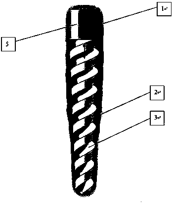
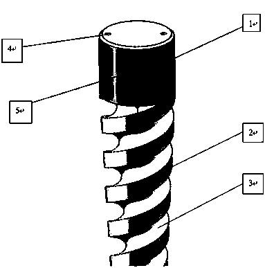
[0012] As shown in the figure, the twist drill includes a drill handle (1) and a drill body (2). The drill handle (1) is set above the drill body (2) and connected with the drill body (2). The clamps on both sides of the conical section The angle is 135°, there are several helical cutting edges on the cutter head, and the helix angle is 20°, and a spiral chip removal groove (3) is formed between the cutting edges, which is conducive to chip removal.

[0013] The upper end of the drill shank (1) is provided with two cooling grooves (4). The two cooling grooves (4) are symmetrical to each other with the axis of the drill body (2) as the center. The cooling liquid groove (4) leads to the drain groove (3 ) on both sides. The abrasive layer (5) can increase the friction between the drill bit and the rotating shaft, so that the drill bit can be clamped more firmly. The outer surface of the drill shank (1) is provided with a frosted layer (5) t...


PUM


Abstract

The present invention designs a twist drill, which is designed in a tapered shape, including a drill shank (1) and a drill body (2), a chip removal groove (3), and two cooling grooves (4). There are two in total, and a chip flute is formed between the rotation paths of the cutting edge. Two cooling grooves (4) are arranged on the top of the drill shank (1), and the cooling liquid grooves (4) lead to both sides of the discharge groove (3). The abrasive layer (5) can increase the friction between the drill bit and the rotating shaft, so that the drill bit can be clamped more firmly. The present invention can cool the whole twist drill without being thrown out due to the rotation of the drill body, has high processing efficiency, good chip removal effect, is beneficial to clamping and is a low-cost twist drill.

Description

technical field [0001] The invention relates to the technical field of cutting tools, in particular to a twist drill. Background technique [0002] The drill bits of twist drills are generally made of high-speed steel, and the production cost is high, which is not conducive to reducing production costs. The chip removal ability of the twist drill reflects the quality of the surface of the hole processed by the twist drill. It will damage the surface of the processed hole, affect the processing effect of the twist drill, and is not conducive to production. The twist drill includes a drill shank and a drill body. If the hole is drilled for a long time, the twist drill needs to be withdrawn from the hole in order to add coolant to the hole; the rotating twist drill enters the hole again, and the coolant can only flow from the chip flute to the hole. The drill body is cooled upwards, and during the drilling process of the twist drill, the coolant will be thrown out, affecting t...

Claims


Application Information

Patent Timeline
Patent Type & Authority Applications(China)
IPC IPC(8): B23B51/02B23B51/06
CPCB23B51/02B23B51/06B23B2251/408
Inventor 陈术前
Owner 陈术前
Why Eureka
Eureka Blog
Learn More