Automatic resistance welding machine

A welding machine, automatic row technology, applied in welding equipment, resistance welding equipment, metal processing equipment and other directions, can solve the problems of danger, difficult to meet production needs, low production efficiency, etc., achieve high automation, save labor, improve production The effect of efficiency

Inactive Publication Date: 2018-02-02
江门市新会区国正机电设备有限公司
View PDF6 Cites 2 Cited by
  • Summary
  • Abstract
  • Description
  • Claims
  • Application Information

AI Technical Summary

Problems solved by technology

[0002] Bent racks are often used in dressing rooms and indoor housing. The number of hooks on the racks is large enough to hang many pieces of towels or clothes; the steel balls and hook bars of the hooks on the racks currently on the market are placed by ha

Method used


Image

  • Automatic resistance welding machine
  • Automatic resistance welding machine
  • Automatic resistance welding machine

Examples


Embodiment Construction

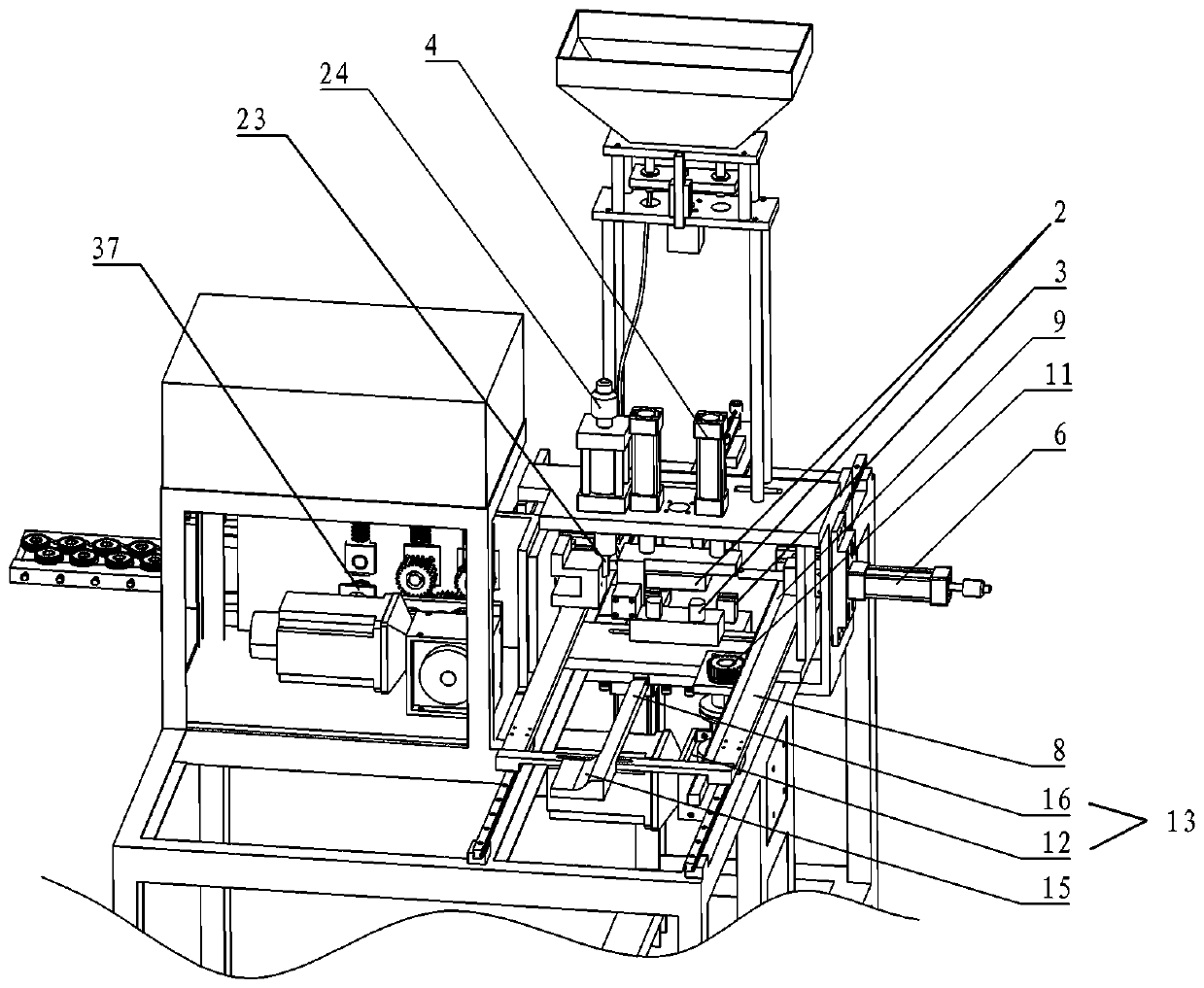
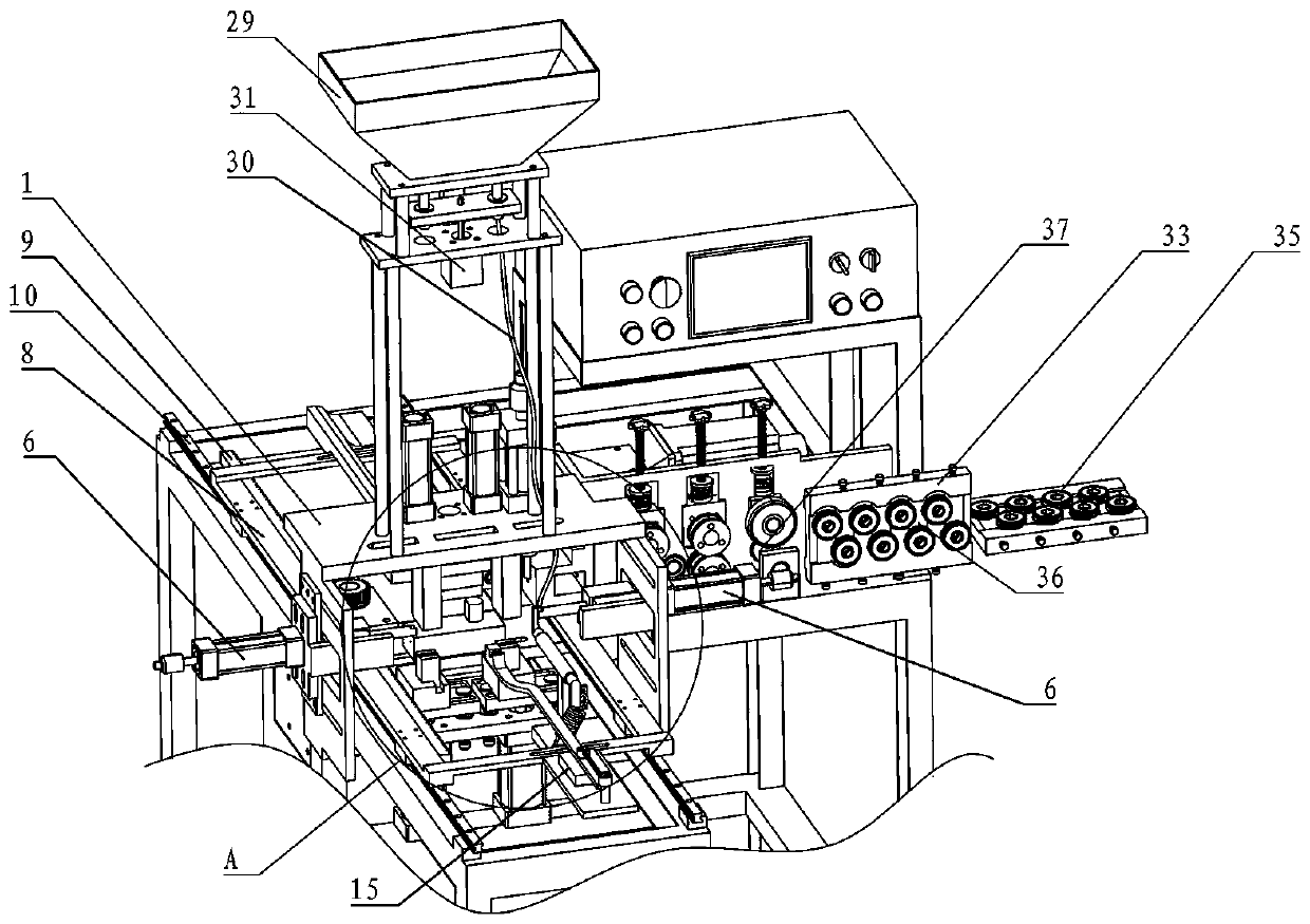
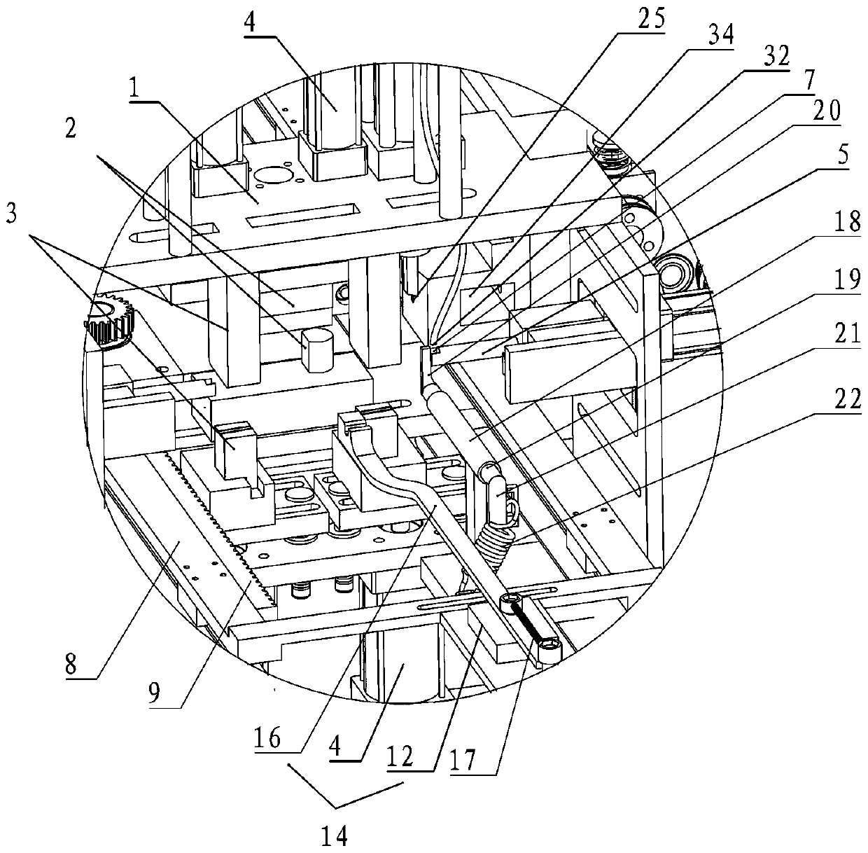
[0021] Such as Figure 1 to Figure 4 As shown, an automatic row welding machine includes a translation mechanism installed with a rack, a welding device, a hook wire feeding device, a hook wire cutting device, a steel ball blanking device, and a steel ball conveying electrode rod 5. The welding device is equipped with There are two groups of butt-welding group I2 and butt-welding group II 3 for respectively welding hook wires and steel balls. The hook wire cutting device is installed on the side of butt-welding group I2, and the outlet 34 of the hook wire feeding device is connected to the hook wire The wire cutting device feed port 25 is connected, the steel ball conveying electrode rod 5 is installed on the side of the butt welding group II3, the steel ball conveying electrode rod 5 is connected with the electrode rod driving device 6, and the discharge port 32 of the steel ball blanking device is located at the steel ball Above the end of the conveying electrode rod 5, the ...


PUM


Abstract

The invention provides an automatic resistance welding machine. The automatic resistance welding machine comprises a horizontal moving mechanism provided with a framed bent, a welding device, a hook wire conveying device, a hook wire cutting device, a steel ball discharging device and a steel ball conveying electrode stem. The welding device is internally provided with a butt-welding set I and a butt-welding set II which are used for welding hook wires and steel balls correspondingly. The hook wire cutting device is installed on the side surface of the butt-welding set I. A wire outlet of thehook wire conveying device is connected with a feeding opening of the hook wire cutting device. The steel ball conveying electrode stem is installed on the side surface of the butt-welding set II andconnected with an electrode stem driving device. A discharging opening of the steel ball discharging device is located above the end part of the steel ball conveying electrode stem. The end part of the steel ball conveying electrode stem is provided with a receiving part. The horizontal moving mechanism is installed on the resistance welding machine and reciprocates at the welding position of thewelding device. The hook wires and the steel balls are welded to the framed bent automatically. The production efficiency is improved, and the labor cost is saved.

Description

technical field [0001] The invention relates to a welding machine, in particular to a processing equipment for automatic welding. Background technique [0002] Bent racks are often used in dressing rooms and indoor housing. The number of hooks on the racks is large enough to hang many pieces of towels or clothes; the steel balls and hook bars of the hooks on the racks currently on the market are placed by hand. Putting it into the welding equipment to weld it as a whole, because it is manual operation, accidents are inevitable, and the production efficiency is low, so it is difficult to meet the current increasing production demand, and there is a certain danger. Contents of the invention [0003] In view of the above-mentioned deficiencies in the prior art, the present invention provides an automatic welding machine, which can automatically weld the hook wires and steel balls to the required position of the rack. [0004] An automatic row welding machine, including a tra...

Claims


Application Information

Patent Timeline
IPC IPC(8): B23K11/00B23K11/36
CPCB23K11/00B23K11/002B23K11/36
Inventor 左国正
Owner 江门市新会区国正机电设备有限公司
Why Eureka
Try Eureka