Threaded column cement pile driver

A technology of cement piles and threaded columns, applied in the field of construction equipment, can solve the problems of waste, multiple raw materials, and reduce the bearing capacity of ground piles, and achieve the effects of improving the utilization rate, reducing the work strength, and improving the bearing capacity of the pile body.

Active Publication Date: 2019-11-29
瑞安市异想天开科技有限公司
View PDF4 Cites 0 Cited by
  • Summary
  • Abstract
  • Description
  • Claims
  • Application Information

AI Technical Summary

Problems solved by technology

[0002] With the development of the urbanization process, high-rise buildings in cities and towns have sprung up like mushrooms after a spring rain; a solid foundation needs to be laid before the construction of the building. For the soft soil layer, the construction team often uses the rotary jet machine to drive the ground piles. , after the cement and soft soil medium solidify, a solid cement mixing pile is formed. The pile body of the cement mixing pile and the soil layer produce a large frictional resistance, which supports the vertical load formed by the building above, so the pile body and the soil layer The contact area directly determines the bearing capacity of the ground pile; the cross-section of the cement mixing pile driven into the construction field is circular at present. Since the circumference of the circle is the smallest under the same area, the cylindrical ground pile The area of ​​the formed pile body is the smallest, and the bearing capacity that can be provided at this time is also the smallest. Therefore, the traditional pile driving and pile formation methods cannot fully utilize the friction force of the soil layer on the pile body, which reduces the bearing capacity of the ground pile and wastes a lot of time. many raw materials

Method used


Image

  • Threaded column cement pile driver
  • Threaded column cement pile driver

Examples


Embodiment

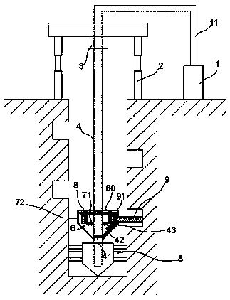
[0022] exist figure 1 , figure 2 In the shown embodiment, this threaded column cement pile driver includes a grouting machine 1, a guide pipe 11, a lifting frame 2, a driving machine 3, and also includes a driving rod 4 installed on the driving machine 3. The end of 4 is equipped with drill bit 5;

[0023] One end of the guide pipe 11 is connected to the grouting machine 1, and the other end extends along the driving rod 4 and communicates with the grouting port on the drill bit 5;

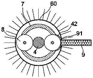
[0024] A threaded drill is provided on the drive rod 4, and the threaded drill includes a dustproof casing 60, and a limit ring 6 is arranged in the dustproof casing 60, and the limit ring 6 is fixedly installed on the On the drive rod 4; an adjustment ring 7 is installed close to the limit ring 6, and the adjustment ring 7 includes a chassis 71 and a ring body 72, and the chassis 71 is sleeved on the drive rod 4; The surface of the chassis 71 and the limit ring 6 are provided with matching ch...


PUM


Abstract

The invention relates to a threaded column cement piling machine. The threaded column cement piling machine comprises a slip casting machine, a flow guide pipe, a lifting support, a driving machine and a driving rod; a thread cutting device is arranged on the driving rod and comprises an adjusting ring, and the adjusting ring is meshed and connected with the driving rod through a reduction gear set; a thread cutting rod is arranged on an outer annular face of the adjusting ring, a driving gear is arranged at the end, connected with the adjusting ring, of the thread cutting rod, and the threadcutting rod can be driven by the driving gear to freely rotate around the axis of the thread cutting rod relative to the adjusting ring; driving lines are further arranged on the driving rod and are meshed and connected with the driving gear through a transmission wheel; and a rotating shaft of the transmission wheel is connected to the adjusting ring through a connecting rod. The cement piling machine is novel in structure and convenient and quick to operate, the pile bearing capacity can be greatly improved, the foundation firmness is strengthened, pile forming raw materials are reduced, andthe building cost is reduced.

Description

technical field [0001] The invention relates to a building construction equipment, in particular to a cement pile driver. Background technique [0002] With the development of the urbanization process, high-rise buildings in cities and towns have sprung up like mushrooms after a spring rain; a solid foundation needs to be laid before the construction of the building. For the soft soil layer, the construction team often uses the rotary jet machine to drive the ground piles. , after the cement and soft soil medium solidify, a solid cement mixing pile is formed. The pile body of the cement mixing pile and the soil layer produce a large frictional resistance, which supports the vertical load formed by the building above, so the pile body and the soil layer The contact area directly determines the bearing capacity of the ground pile; the cross-section of the cement mixing pile driven into the construction field is circular at present. Since the circumference of the circle is the ...

Claims


Application Information

Patent Timeline
Patent Type & Authority Patents(China)
IPC IPC(8): E02D5/46E21B3/02
CPCE02D5/46E02D2250/003E21B3/02
Inventor 钱娟娟
Owner 瑞安市异想天开科技有限公司
Why Eureka
Try Eureka