Automatic control hydraulic pump testing system and method

A testing system and hydraulic system technology, which is applied in fluid pressure actuation system testing, fluid pressure actuating devices, mechanical equipment, etc., can solve the problems of low testing frequency, low degree of automatic operation, and high labor intensity of testers, and achieve High degree of automation, simple structure, solve the effect of low degree of automation operation

Active Publication Date: 2018-02-02
BEIJING TIANMA INTELLIGENT CONTROL TECH CO LTD +1
View PDF6 Cites 3 Cited by
  • Summary
  • Abstract
  • Description
  • Claims
  • Application Information

AI Technical Summary

Problems solved by technology

However, the current hydraulic system and its key components for the factory performance testing of hydraulic pumps are relatively backward
[0003] figure 1 It is a schematic diagram of the structure of the hydraulic valve for pressure regulation of the hydraulic system widely used in the market. It is a typical pilot relief valve. It has the following disadvantages in the hydraulic system test process: the pressure of the hydraulic system is adjusted manually. The screw adjustment method has a low degree of automation; the operation in the high-pressure hydraulic system seriously threatens the life safety of the operator
Traditional operation methods include manual operation or mechanical unloading. Manual operation requires high labor intensity for testers, low test frequency, and certain potential safety hazards.
The mechanical unloading operation method also has disadvantages such as low test frequency and low degree of automation

Method used


Image

  • Automatic control hydraulic pump testing system and method
  • Automatic control hydraulic pump testing system and method
  • Automatic control hydraulic pump testing system and method

Examples


Embodiment 1

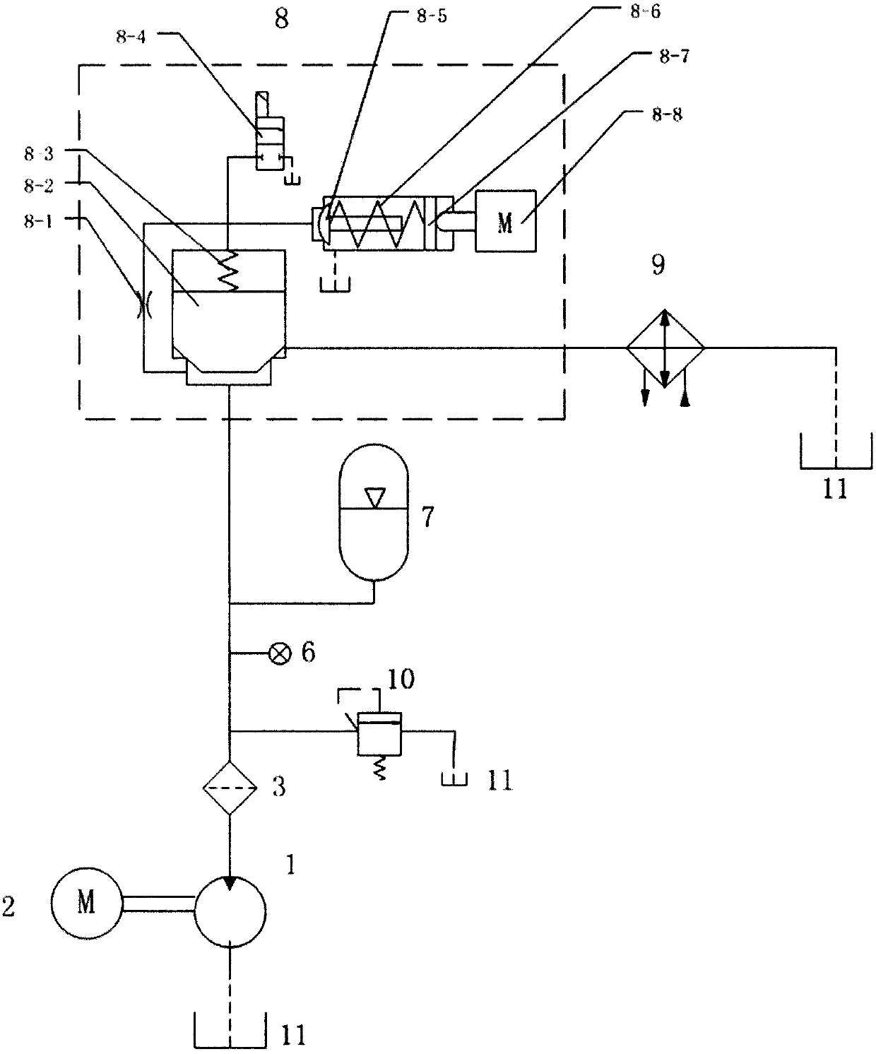
[0039] figure 2 It is the principle diagram of the tested hydraulic pump testing system of the present invention, which mainly includes: 1-tested hydraulic pump; 2-drive motor; 3-filter; 6-pressure sensor; 7-accumulator; 8-digital regulator Pressure valve; 9-cooler; 10-safety valve; 11-liquid tank.

[0040] The drive motor 2 drives the tested hydraulic pump 1 to absorb liquid from the liquid tank 11, and the oil returns to the liquid tank after passing through the filter 3 digital pressure regulating valve 8 and the cooler 9; Pressure sensor 6, accumulator 7 and safety valve 10.

[0041] Among them, the filter filters the oil, the accumulator stabilizes the outlet pressure and flow pulsation of the hydraulic pump, the pressure sensor feeds back the system pressure, cooperates with the upper computer software to realize the automatic control of the system, the cooler cools the oil, and the safety valve plays a role in the system. overload protection.

Embodiment 2

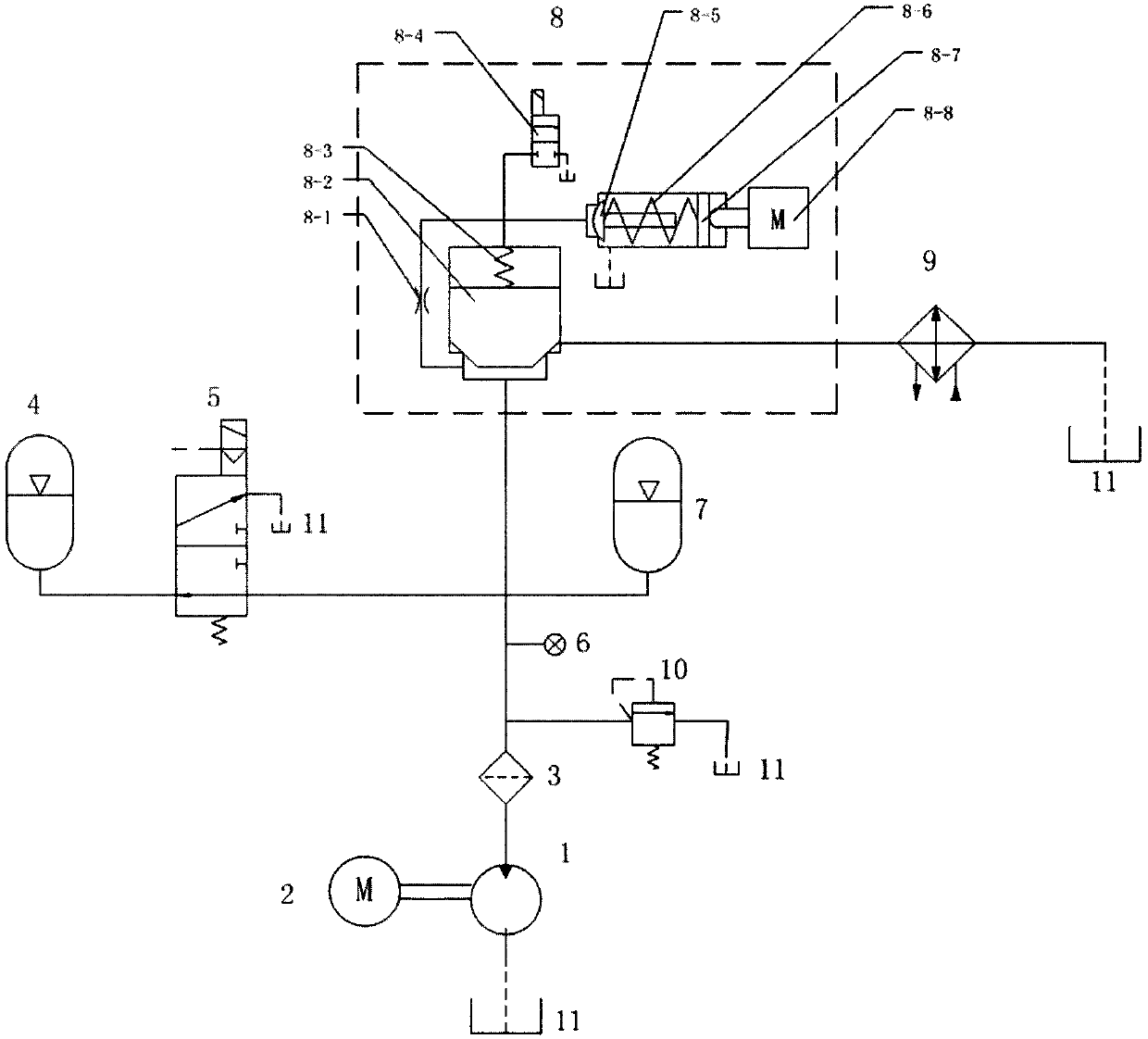
[0043] Such as image 3 As shown, an accumulator group is set at the outlet of the tested hydraulic pump 1, and the accumulator group includes an accumulator 7 and a second accumulator 4 connected in parallel, wherein a pilot type electromagnetic converter is connected in series before the accumulator 4 Directional valve 5; wherein the second accumulator 4 is an accumulator with low restart pressure, and accumulator 7 is an accumulator with high restart pressure

[0044] The tested hydraulic pump test system is realized by the following methods:

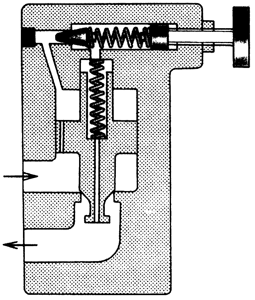
[0045] When the hydraulic system starts, the driving motor 2 drives the hydraulic pump 1 to suck liquid from the liquid tank 11. At this time, the software of the host computer sends a control signal to the solenoid pilot valve 8-4 of the digital pressure regulating valve, and the digital pressure regulating valve The spool of the electromagnetic pilot valve 8-4 changes direction, and the oil enters the front chamber of the main spo...


PUM


Abstract

The invention relates to an automatic control hydraulic pump testing system and method which are used for conducting performance testing on a tested hydraulic pump. The tested hydraulic pump is connected with an energy accumulator in series, oil discharged from the hydraulic pump is adjusted by a digital pressure regulating valve and then returns to a liquid box through a cooling device, the digital pressure regulating valve has the effect of adjusting the outlet pressure of the tested hydraulic pump, and the performance of the tested hydraulic pump under different pressure conditions is verified. A control signal is transmitted to an electromagnetic pilot operated valve of the digital pressure regulating valve, and no-load starting of the testing system can be achieved. A control signal is transmitted to a linear stepping motor through upper computer software, the stretchable amount of a linear motor shaft is adjusted, the opening pressure of the electromagnetic pilot operated valve is adjusted, and therefore the hydraulic system reaches different pressure stages.

Description

technical field [0001] The invention relates to a hydraulic pump testing system, in particular to an automatically controlled pressure regulating system for hydraulic pump testing. Background technique [0002] With the continuous advancement of technology, the nominal pressure of various hydraulic pumps is constantly developing towards high pressure. However, the hydraulic system and its key components for the factory performance testing of hydraulic pumps are relatively backward. [0003] figure 1 It is a schematic diagram of the structure of the hydraulic valve for pressure regulation of the hydraulic system widely used in the market. It is a typical pilot relief valve. It has the following disadvantages in the hydraulic system test process: the pressure of the hydraulic system is adjusted manually. The screw adjustment method has a low degree of automation; the operation in the high-pressure hydraulic system seriously threatens the life safety of the operator. [0004...

Claims


Application Information

Patent Timeline
Patent Type & Authority Applications(China)
IPC IPC(8): F15B19/00
CPCF15B19/005
Inventor 刘文超李俊士韦文术牛剑锋王伟周如林李然刘杰王松杨立吴桐
Owner BEIJING TIANMA INTELLIGENT CONTROL TECH CO LTD
Why Eureka
Try Eureka