A rack-mounted fiber optic cable jumper storage box

A storage box and rack-mounted technology, which is applied in the field of optical fiber communication, can solve the problems of dense and complex wiring and fiber routing, inconvenient installation, maintenance and management, and impact on quality, so as to avoid excessive decibel attenuation of optical signals and good optical quality. Signal transmission quality, the effect of reducing the degree of crossover

Active Publication Date: 2020-12-22
BAZHONG POWER SUPPLY COMPANY OF STATE GRID SICHUAN ELECTRIC POWER
View PDF10 Cites 0 Cited by
  • Summary
  • Abstract
  • Description
  • Claims
  • Application Information

AI Technical Summary

Problems solved by technology

However, most of the optical fiber distribution frames using light with such a small radius of curvature are in the research and development stage; in addition, the increase in the capacity of the optical fiber unit box will greatly increase the number of optical fiber cables and jumper fibers, resulting in more dense and complex wiring and fiber routing. , which brings inconvenience to the operation
[0003] The fiber jumper between the traditional fiber distribution frames needs to pass through the fiber rack on the top of the machine room, and a large amount of space needs to be reserved in the rack for storing redundant fiber jumpers, and the production cost is high; and this fiber distribution frame The wiring of the fiber jumper is complicated and there are many crossovers, which will not only cause the radius of curvature of the fiber jumper to be small, affect the quality, but also bring inconvenience to installation, maintenance and management

Method used


Image

  • A rack-mounted fiber optic cable jumper storage box
  • A rack-mounted fiber optic cable jumper storage box
  • A rack-mounted fiber optic cable jumper storage box

Examples


Embodiment

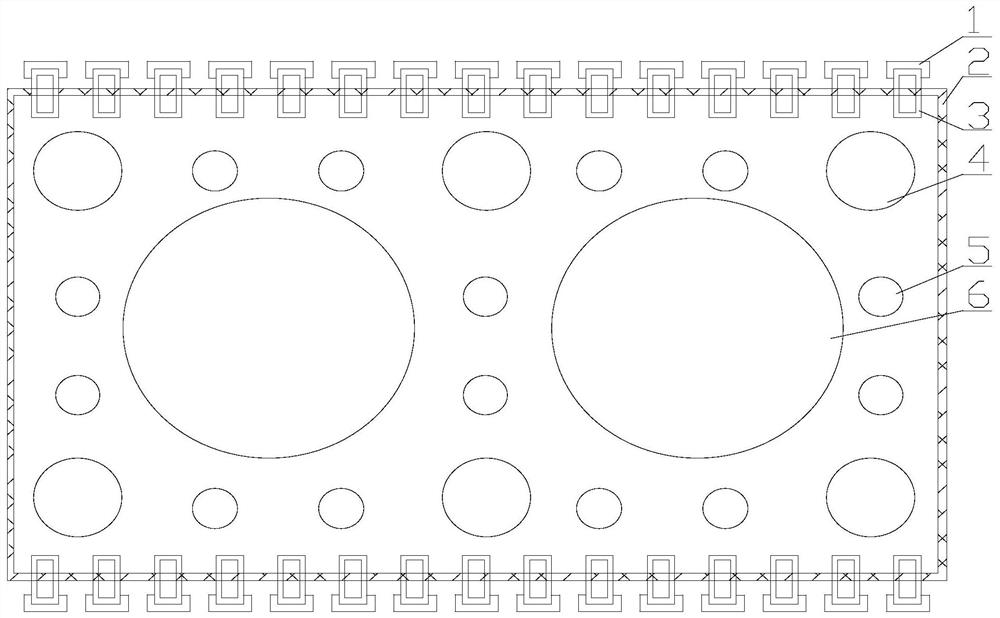
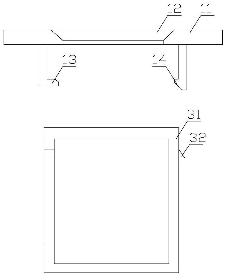
[0028] Such as Figure 1 to Figure 4 As shown, a rack-mounted optical cable jumper storage box includes a housing 2, the housing 2 is a cuboid structure, and the same number of fixing devices 3 are arranged on both sides of the housing 2 in the longitudinal direction, and the fixing devices 3 are used For the entry and exit of fiber jumpers; there are two first winding columns 6 of cylindrical structure on the inner side of the housing 2, the housing 2 has two 1 / 4 split lines in the long direction, and a 1 / 4 branch line in the short direction of the housing 2 / 2 line, two long 1 / 4 lines and a short 1 / 2 line form a left intersection and a right intersection, and the centers of the two first winding columns 6 are respectively at the left intersection and the right intersection On the point; shell 2 has two 1 / 16 points in the long direction, shell 2 has two 1 / 8 points in the short direction, two long 1 / 16 points and two short 1 / 8 points Form the left front intersection, right fr...


PUM


Abstract

The invention provides a rack type optical fiber patch cord accommodating box comprising a shell in the shape of a cuboid. The two sides in the length direction of the shell are provided with fixing devices with the same number; the inner side of the shell is provided with two first winding posts with a cylindrical structure; the shell has two 1 / 4 lines in the long side direction and one 1 / 2 linein the short side direction, wherein the two long side direction 1 / 4 lines and the short side direction 1 / 2 line form a left intersecting point and a right intersecting point and the centers of circleof the two first winding posts are located on the left intersecting point and the right intersecting point; the shell has two 1 / 16 lines in the long side direction and two 1 / 8 lines in the short sidedirection, wherein the two long side direction 1 / 16 lines and the two short side direction1 / 8 lines form a left front intersecting point, a right front intersecting point, a left rear intersecting point and a right rear intersecting point. The rack type optical fiber patch cord accommodating box reduces the complexity of patch cords therein and reduces the intersecting degree of patch cords, thereby guaranteeing that the radius of curvature is in a range as high as possible, preventing excessive signal attenuation decibels caused by extremely small radiuses of curvature and guaranteeing highoptical signal transmission quality.

Description

technical field [0001] The invention relates to the field of optical fiber communication, in particular to a rack-type optical cable jumper storage box. Background technique [0002] With the development of FTTX, the number of optical fibers in the computer room is increasing, and higher requirements are placed on the manageability of fiber jumpers, which makes the use of traditional optical distribution frames (Optical Distribution Frame, ODF) a great challenge. . At the same time, with the increasing shortage of computer room land, the expensive use of space in the computer room also puts forward better capacity requirements for optical fiber distribution frames. The appearance of optical fibers with small curvature radius provides convenience for further increasing the capacity of optical distribution frames. However, most of the optical fiber distribution frames using light with such a small radius of curvature are in the research and development stage; in addition, th...

Claims


Application Information

Patent Timeline
Patent Type & Authority Patents(China)
IPC IPC(8): G02B6/44
CPCG02B6/4446G02B6/4452G02B6/4454
Inventor 石群旭粟秋成何耀周聪李发均
Owner BAZHONG POWER SUPPLY COMPANY OF STATE GRID SICHUAN ELECTRIC POWER
Why Eureka
Try Eureka