Method for testing and computing optical axis inclination of focusing camera-shooting modules

A technology of a camera module and a calculation method, applied in optics, photography, instruments, etc., can solve the problem that the inclination of the optical axis cannot be obtained, and it is impossible to quantitatively determine the specific position and the repair modulus or replenishment of the lens holder. The amount of glue and the direction of inclination cannot be quantified, etc.

Active Publication Date: 2018-02-02
NINGBO SUNNY OPOTECH CO LTD
View PDF4 Cites 16 Cited by
  • Summary
  • Abstract
  • Description
  • Claims
  • Application Information

AI Technical Summary

Problems solved by technology

This estimation method considers that the tilt of the optical axis of the adjustable-focus camera module is approximately equal to the maximum difference between the four tilt heights divided by the diagonal distance of the field of view of the chip of 0.8, but this estimation method cannot obtain an accurate tilt of the optical axis size, and the direction of inclination cannot be quantified, and the measurement lacks credibility
Moreover, when it is necessary to perform mold repair or glue replenishment on the lens base of the camera module to correct the tilt of the optical axis, this estimation method cannot quantitatively determine the specific position and amount of mold repair or glue replenishment of the mirror base, and there is a problem A large number of subjective factors are not conducive to the improvement of the camera module manufacturing process

Method used


Image

  • Method for testing and computing optical axis inclination of focusing camera-shooting modules
  • Method for testing and computing optical axis inclination of focusing camera-shooting modules
  • Method for testing and computing optical axis inclination of focusing camera-shooting modules

Examples


Embodiment Construction

[0070] The following description serves to disclose the present invention to enable those skilled in the art to carry out the present invention. The preferred embodiments described below are only examples, and those skilled in the art can devise other obvious variations. The basic principles of the present invention defined in the following description can be applied to other embodiments, variations, improvements, equivalents and other technical solutions without departing from the spirit and scope of the present invention.

[0071] It can be understood that the term "a" should be understood as "at least one" or "one or more", that is, in one embodiment, the number of an element can be one, while in another embodiment, the number of the element The quantity can be multiple, and the term "a" cannot be understood as a limitation on the quantity.

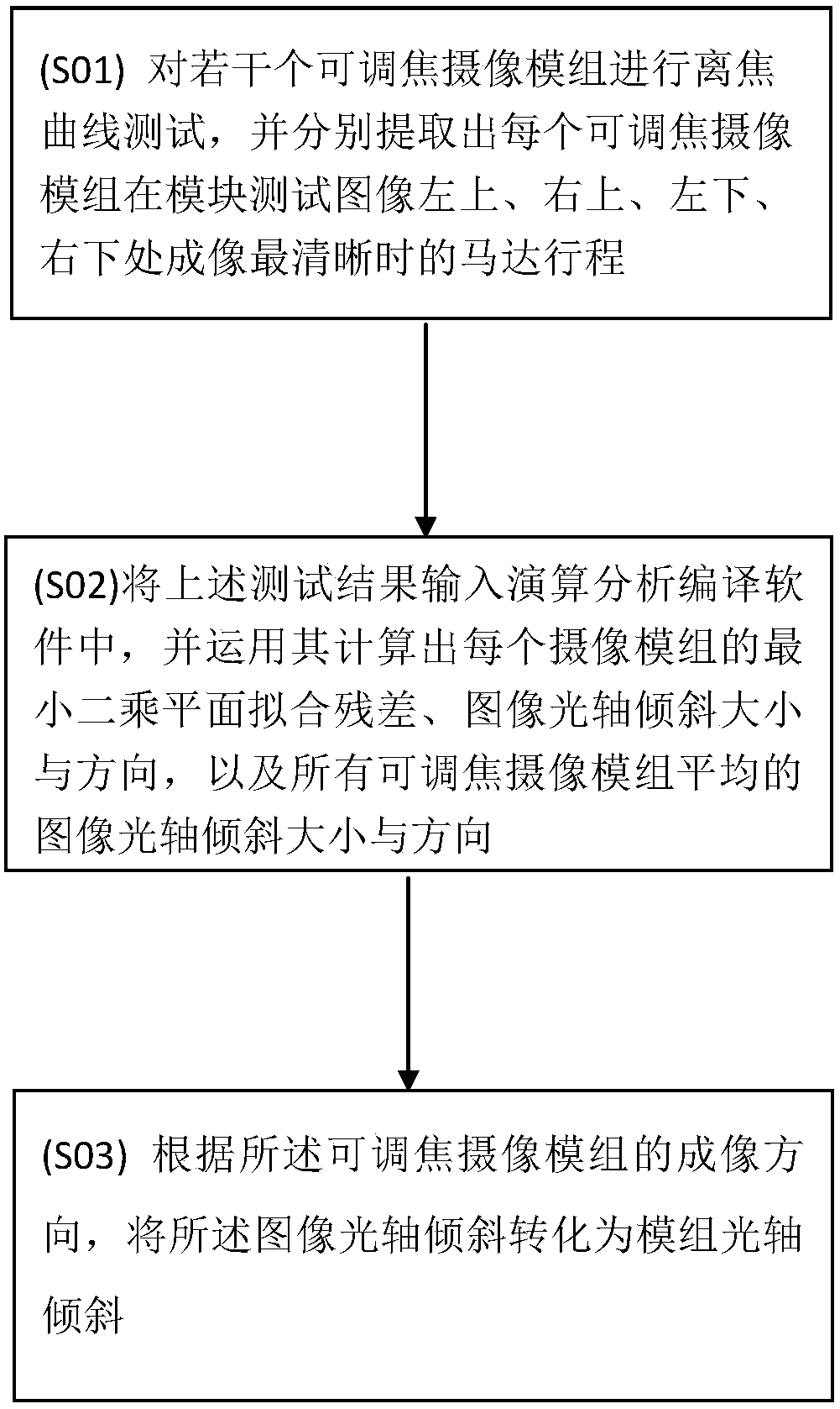
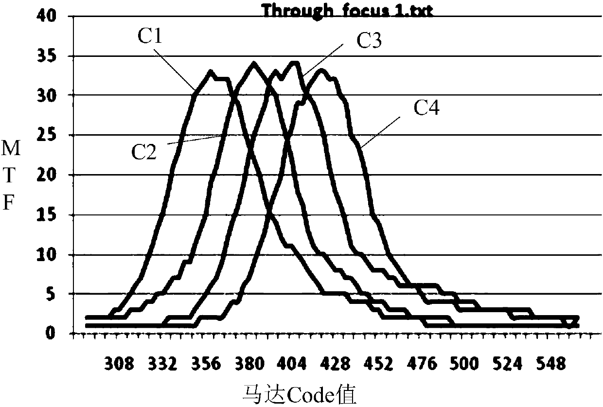
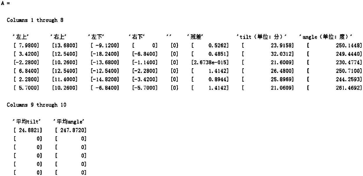
[0072] Such as Figure 1 to Figure 5 As shown, a method for testing and calculating the optical axis tilt of an adjustable focus ca...


PUM


Abstract

The invention discloses a method for testing and computing optical axis inclination of focusing camera-shooting modules. The method comprises the following steps: (S01) carrying out out-of-focus curvetesting on a plurality of focusing camera-shooting modules, and extracting the motor journey of each focusing camera-shooting module when the imaging of module testing images is as clearly as possible at the left upper, right upper, left lower and right lower positions; (S02) inputting the testing result into a calculation analysis compiling software, and using the testing result to compute a least square plane fitting residual of each camera-shooting module, the inclined size and direction of an image optical axis and the inclined size and direction of the average image optical axis of all the focusing camera-shooting cameras; and (S03) according to the imaging direction of the focusing camera-shooting modules, converting the optical axis inclination of the images into the optical axis inclination of the modules.

Description

technical field [0001] The invention relates to the technical field of camera modules, in particular to a method for testing and calculating the tilt of the optical axis of an adjustable-focus camera module. Background technique [0002] Resolution is the ability to distinguish the details of the original subject. Furthermore, the resolution is a physical quantity used to describe the ability of the microfilm system to reproduce the subtle parts of the original, and it is an important index for image quality evaluation. In other words, the resolution is the most important performance parameter of the adjustable-focus camera module, and the main factors affecting the resolution of the adjustable-focus camera module are the matching between the lens and the photosensitive chip, motor performance, incoming material tolerance, assembly tolerance, etc. . In addition, the optical axis tilt of the adjustable focus camera module is an important index for studying the resolution of...

Claims


Application Information

Patent Timeline
IPC IPC(8): G03B43/00
CPCG03B43/00
Inventor 丁亮蒋恒
Owner NINGBO SUNNY OPOTECH CO LTD
Why Eureka
Try Eureka