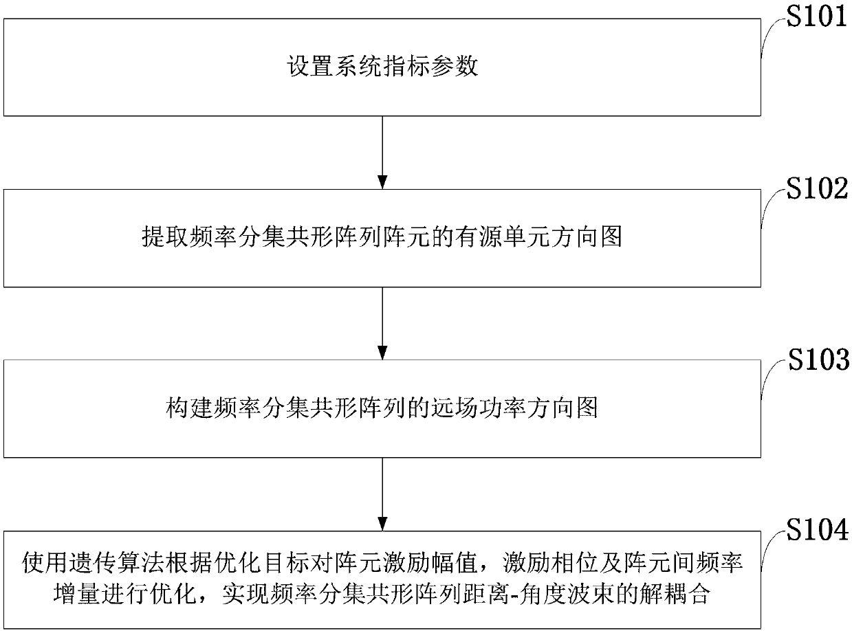
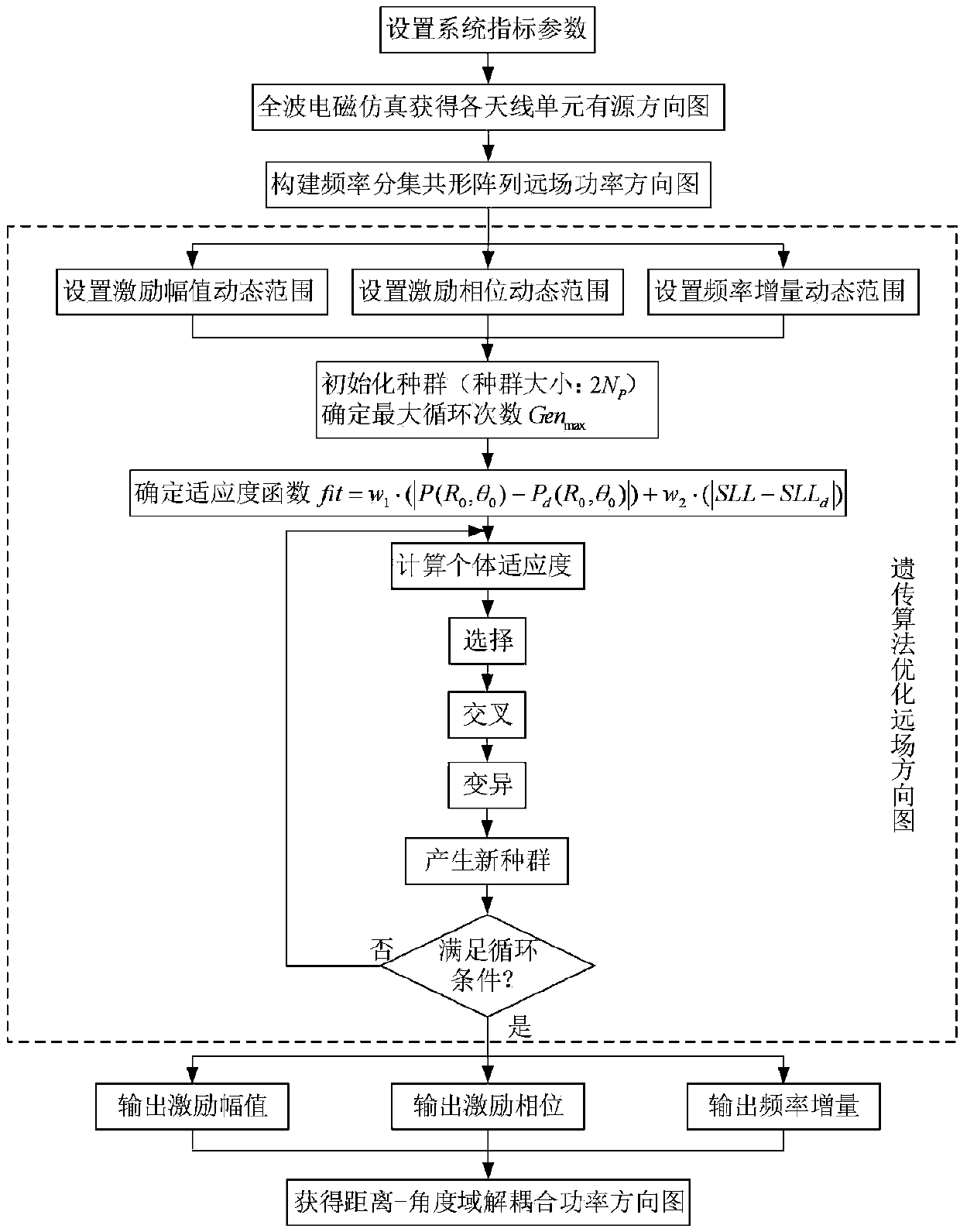
Decoupling method based on genetic algorithm for frequency diversity conformal array beam and antenna
A frequency diversity, conformal array technology, applied in the field of radar antennas, can solve the problems of limited application, energy can not be concentrated in the target area, and the radar has poor adaptability to complex environments.
- Summary
- Abstract
- Description
- Claims
- Application Information
AI Technical Summary
Problems solved by technology
Method used
Image

Examples
Embodiment 1
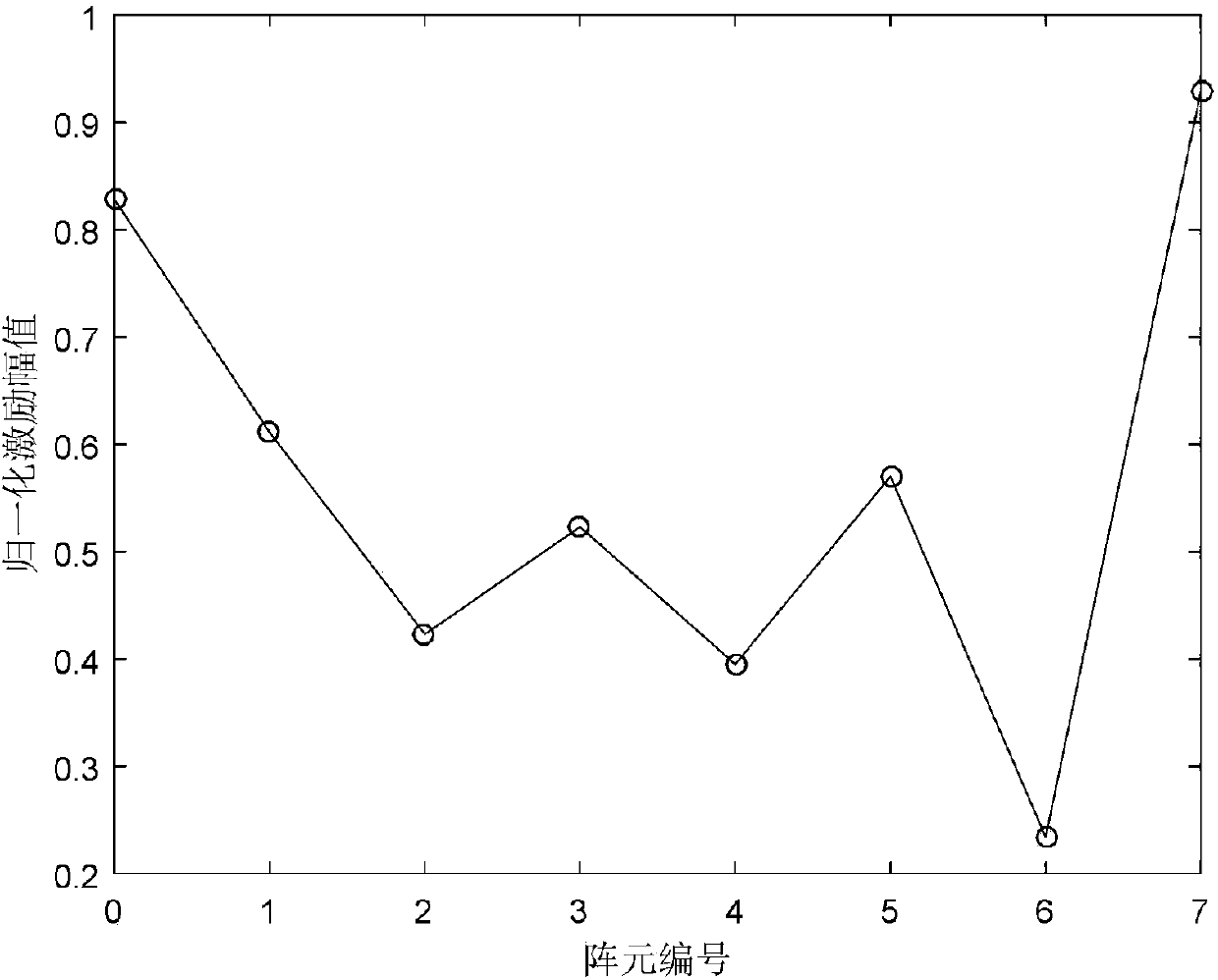
[0121] Embodiment 1: Set the array element number N=8 of the frequency diversity conformal array, and the center frequency f 0 =10GHz, array element spacing d=0.5λ, conformal surface is a cylindrical surface with radius Radius=3.33λ, λ is the wavelength of the electromagnetic wave in the air at the center frequency, The array unit adopts a microstrip patch antenna working at 10GHz, and the dynamic range of the normalized excitation amplitude of the array element is [a min ,a max ]=[0.1,1], the dynamic range of the excitation phase is [φ min ,φ max ]=[0,2π], the dynamic range of the frequency increment is [Δf min ,Δf max ]=[2kHz,10kHz], the angle and distance of the target are respectively θ 0 = 0°, R 0 =70km.
[0122] Under the above-mentioned simulation parameters, the method of the present invention is adopted to optimize the far-field power pattern of the frequency diversity conformal array, and its final normalized excitation amplitude A n The distribution of ima...
Embodiment 2
[0123] Embodiment 2: Set the array element number N=18 of frequency diversity conformal array, center frequency f 0 =10GHz, array element spacing d=0.5λ, the conformal surface is a cylindrical surface with a radius of Radius=6.67λ, λ is the wavelength of the electromagnetic wave in the air at the center frequency, The array unit adopts a microstrip patch antenna working at 10GHz, and the dynamic range of the normalized excitation amplitude of the array element is [a min ,a max ]=[0.1,1], the dynamic range of the excitation phase is [φ min ,φ max ]=[0,2π], the dynamic range of the frequency increment is [Δf min ,Δf max ]=[2kHz,15kHz], the angle and distance of target 1 are θ 1 = -30°, R 1 =50km, the angle and distance of target 2 are θ 2 = 60°, R 2 =70km.
[0124] Under the above-mentioned simulation parameters, the method of the present invention is adopted to optimize the far-field power pattern of the frequency diversity conformal array, and its final normalized ex...
PUM
 Abstract
Description
Claims
Application Information
 - R&D
- Intellectual Property
- Life Sciences
- Materials
- Tech Scout
- Unparalleled Data Quality
- Higher Quality Content
- 60% Fewer Hallucinations
Browse by: Latest US Patents, China's latest patents, Technical Efficacy Thesaurus, Application Domain, Technology Topic, Popular Technical Reports.
© 2025 PatSnap. All rights reserved.Legal|Privacy policy|Modern Slavery Act Transparency Statement|Sitemap|About US| Contact US: help@patsnap.com