Semiconductor ion energy generation method

A semiconductor and ion energy technology, applied in the field of semiconductor ion energy power generation, can solve the problems of environmental pollution, resource consumption, low efficiency, etc., and achieve the effect of not polluting the environment and producing no noise

Inactive Publication Date: 2018-02-02
徐希尧 +1
View PDF0 Cites 4 Cited by
  • Summary
  • Abstract
  • Description
  • Claims
  • Application Information

AI Technical Summary

Problems solved by technology

[0003] ①Electromagnetic power generation: by consuming fossil fuels to generate kinetic energy (thermal power plant), by converting nuclear energy into kinetic energy (nuclear power plant), by converting potential energy into kinetic energy (hydraulic power plant), and by other means, sea wave, tidal, and wind power can be driven by kinetic energy Electromagnetic generators generate electricity, but the disadvantages are resource consumption, environmental pollution, and discontinuity;
[0004] ②Chemical energy power generation...

Method used


Image

  • Semiconductor ion energy generation method
  • Semiconductor ion energy generation method
  • Semiconductor ion energy generation method

Examples


Embodiment 1

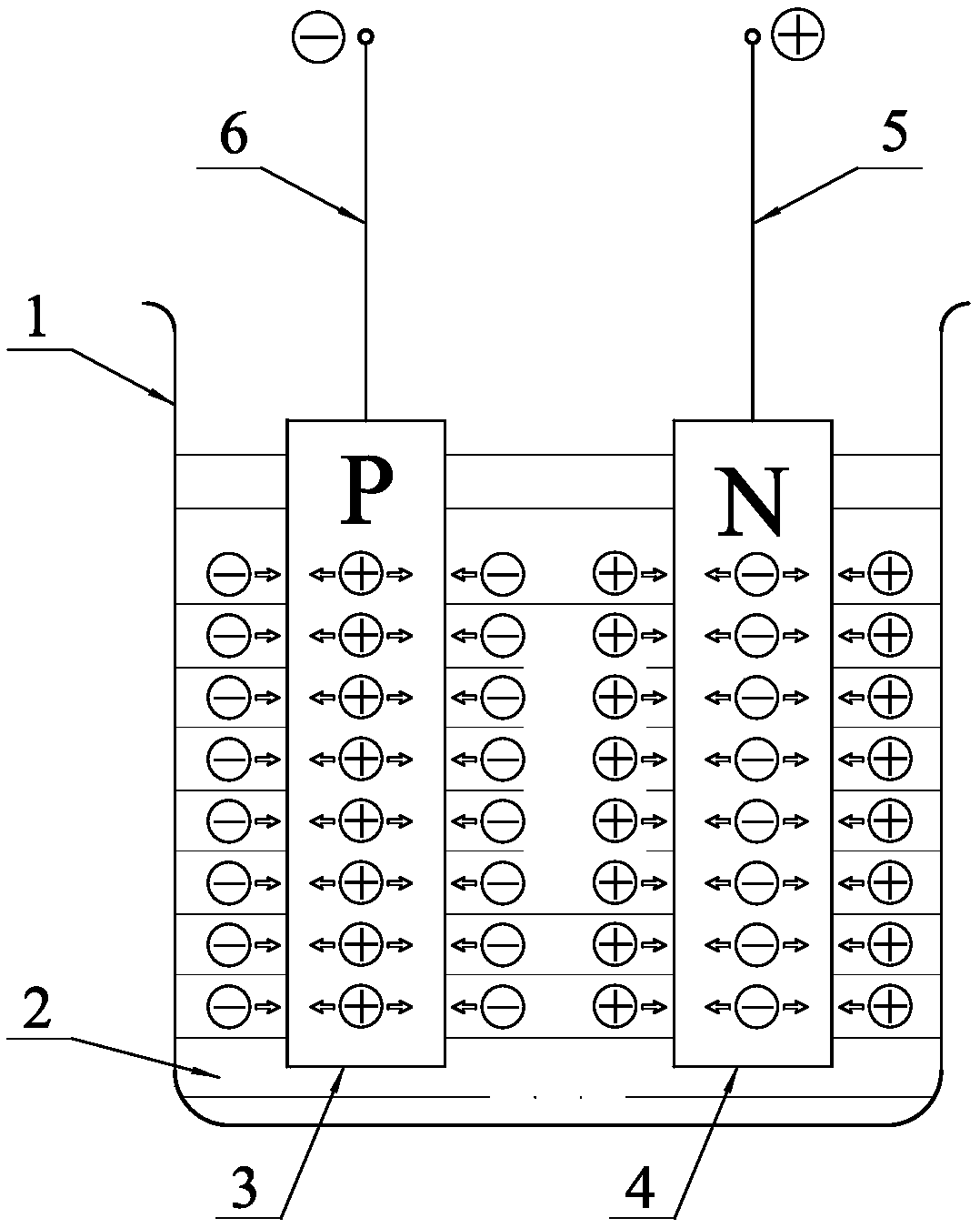
[0036] Such as figure 1 As shown, the semiconductor ion power generation method described in the present embodiment, ionic liquid 2 is built into the container 1, and then a group of power generation units are built into the ionic liquid 2, and the power generation unit includes a pair of P-type semiconductor chips 3 and The N-type semiconductor sheet 4, the electric field of the P-type semiconductor sheet 3 and the N-type semiconductor sheet 4 interact with the ionic electric field in the ionic liquid 2, and the positively charged ions in the ionic liquid 2 flow to the N-type semiconductor sheet 4 under the action of the electric field, Negatively charged ions in the ionic liquid 2 flow to the P-type semiconductor sheet 3 under the action of an electric field, and the conductive ends are respectively connected by the P-type semiconductor sheet 3 and the N-type semiconductor sheet 4, figure 1 The middle conducting end adopts wires, which are the positive electrode lead 5 drawn...

Embodiment 2

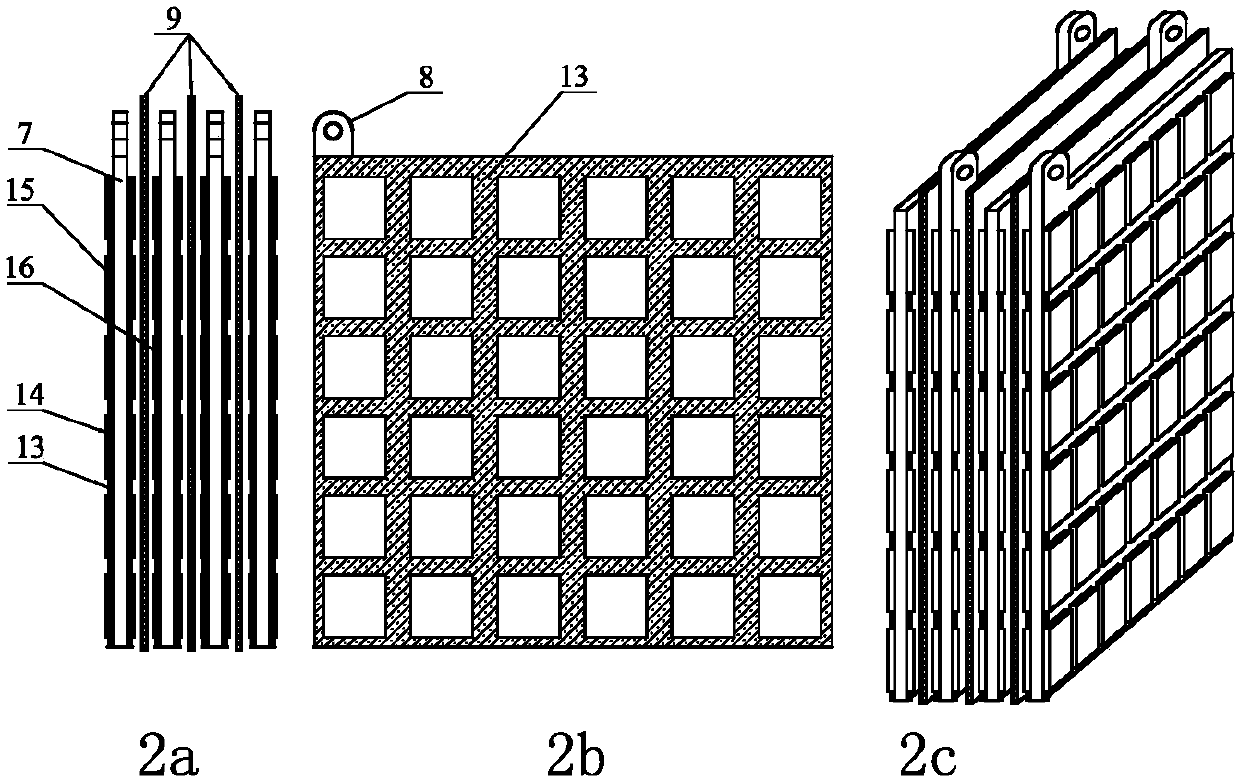
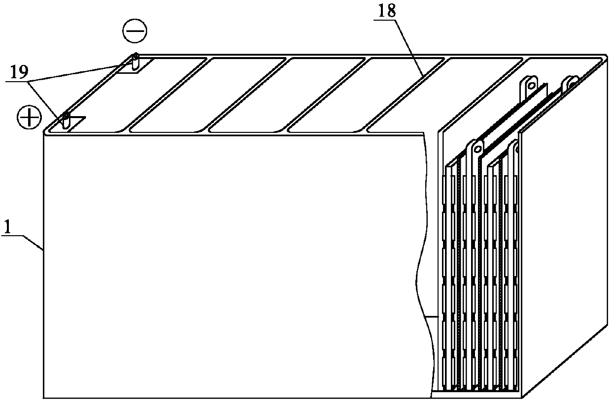
[0039] Such as Figure 2-3 As shown, the present embodiment increases the number of P-type semiconductor slices 3 and N-type semiconductor slices 4 on the basis of Embodiment 1, such as figure 2 As shown, the P-type semiconductor sheet 3 includes two layers, and the two-layer P-type semiconductor sheet 3 is respectively fixed on the two sides of the conductive substrate 7, and the conductive substrate 7 is provided with a pole 8, and the conductive substrate 7 is opposite to the P Type semiconductor chip 3 or N-type semiconductor chip 4 plays a supporting role, and the material can be selected as metal copper; On the substrate 7, the gap between the P-type semiconductor unit pieces 15 is filled with an insulating sealant 13, and the conductive substrate 7 is coated with an insulating sealant 13 on the exposed part of the ionic liquid 2, so as to ensure that the conductive substrate 7 is insulated and conductive to the ionic liquid 2 The glue 14 can be conductive silver glue ...

Embodiment 3

[0042] Such as Figure 4 As shown, on the basis of Embodiment 1, the present invention replaces the P-type semiconductor sheet 3 with an active metal sheet 10. The active metal sheet 10 can be made of aluminum, iron, zinc, etc. Taking metal aluminum as an example, the densely doped When the N-type semiconductor sheet 4 and metal aluminum are placed in the ionic liquid 2, because there is a large amount of electrons in the N-type semiconductor sheet 4, there are very few free electrons in the metal aluminum, and there are almost no holes. Positive ion charges are exchanged with the electronic field of N-type semiconductor sheet 4 under the action of ion electric field, a large amount of positive ion charges enter N-type semiconductor sheet 4, and a large number of electrons in N-type semiconductor sheet 4 enter ionic liquid 2 to form a current, through the conduction The terminal is connected to the electric load to supply power to the load. This power generation method has a f...


PUM


Abstract

The present invention relates to a power generation method; in particular, to a semiconductor ion energy power generation method, specifically: ionic liquid is placed in a container, and then at least one group of power generation units are built into the ionic liquid, and each power generation unit is separated by a partition wall. The power generation unit comprises at least one pair of P-type semiconductor slices and N-type semiconductor slices arranged in pairs, a partition is arranged between the P-type semiconductor slices and the N-type semiconductor slices, and the electric field of the P-type semiconductor slices and the N-type semiconductor slices is in contact with the ionic liquid. The ion-electric field interaction of the ionic liquid, the positively charged ions in the ionic liquid flow to the N-type semiconductor sheet under the action of the electric field, and the negatively charged ions in the ionic liquid flow to the P-type semiconductor sheet under the action of the electric field. The type semiconductor chip is connected to the conductive terminal. The invention does not consume extra energy, does not pollute the environment, does not generate noise, and can generate electricity continuously.

Description

technical field [0001] The invention relates to a power generation method; in particular, it relates to a semiconductor ion energy power generation method. Background technique [0002] There are three basic ways to generate electric energy in the world today: electromagnetic power generation, chemical energy power generation, and photovoltaic solar cell power generation. [0003] ①Electromagnetic power generation: by consuming fossil fuels to generate kinetic energy (thermal power plant), by converting nuclear energy into kinetic energy (nuclear power plant), by converting potential energy into kinetic energy (hydraulic power plant), and by other means, sea wave, tidal, and wind power can be driven by kinetic energy Electromagnetic generators generate electricity, but the disadvantages are resource consumption, environmental pollution, and discontinuity; [0004] ②Chemical energy power generation: various acid-base salt batteries, etc., also consume resources and pollute t...

Claims


Application Information

Patent Timeline
IPC IPC(8): H02N3/00
CPCH02N3/00
Inventor 徐希尧宋辉
Owner 徐希尧
Why Eureka
Try Eureka