Eureka AIR delivers breakthrough ideas for toughest innovation challenges, trusted by R&D personnel around the world.

Manufacturing method of multiposition microwave reactor with reflection cavity

The technology of a microwave reactor and a reflective cavity is applied in the field of scientific experiments, which can solve the problems of reducing the microwave absorption rate and the large difference in microwave absorption, and achieves the effects of easy temperature control, increased application value, and improved microwave utilization.

Inactive Publication Date: 2018-02-06
YUNNAN MINZU UNIV
View PDF7 Cites 6 Cited by
  • Summary
  • Abstract
  • Description
  • Claims
  • Application Information

AI Technical Summary

Problems solved by technology

For multi-position reactors, the best way to adopt is to set the center of the microwave applicator and set the reactor close to the surroundings. The problem is that the microwaves radiated by the microwave applicator pass through the reactor and react in different directions. In the junction of the reactor and fed into the sample, the microwave absorption varies greatly, and there are multiple weak absorption directions, so in different directions, the microwave absorption rate of the material in the reactor is reduced

Method used


Image

  • Manufacturing method of multiposition microwave reactor with reflection cavity
  • Manufacturing method of multiposition microwave reactor with reflection cavity
  • Manufacturing method of multiposition microwave reactor with reflection cavity

Examples


Embodiment Construction

[0019] The present invention will be further described in detail below in conjunction with the accompanying drawings and specific embodiments.

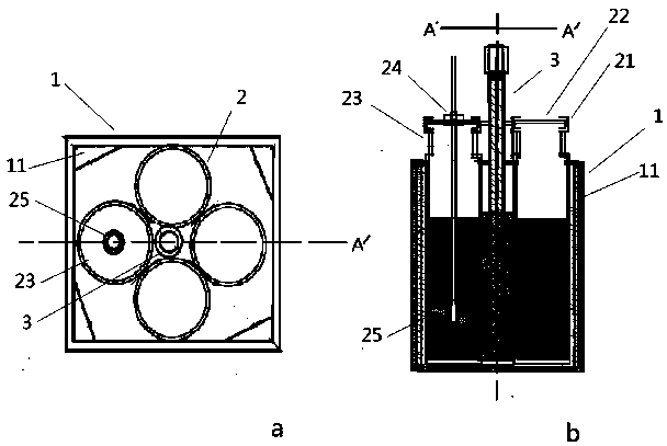
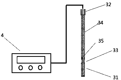
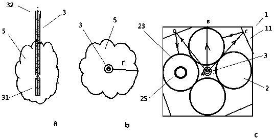
[0020] Such as figure 1 As shown, a multi-position microwave reactor with a reflective cavity includes a reflective cavity, a reactor assembly and a microwave radiator assembly. It is characterized in that the reflective cavity is made of microwave reflective material and has a square tubular cross section Housing 1, the four corners of the tubular housing 1 are provided with microwave reflectors 11; the reactor assembly includes four tubular reactors 2 arranged side by side with a square cross-section, the diagonal of the square cross-section and the The cross-section diagonals of the reflecting cavity are vertically arranged in the tubular housing 1; the microwave radiator assembly includes a microwave radiation head 3 and a microwave source 4, and the radiation head 3 is a rod-shaped slot antenna radiator with a radiation end 31 I...


PUM


Abstract

The invention discloses a multiposition microwave reactor with a reflection cavity. The multiposition microwave reactor comprises the reflection cavity, a reactor subassembly and a microwave radiatorsubassembly and is characterized in that the reflection cavity is a tubular shell which is made of a microwave reaction material and has the cross section being square; microwave reaction bodies are arranged at the four corners of the tubular shell respectively; the reactor subassembly comprises four tubular reactors which are arranged side by side and have the cross sections being square; a diagonal line of the square cross section of the reactor subassembly and a diagonal line of the cross section of the reflection cavity are arranged in the tubular shell in a mutual perpendicular manner; the microwave radiator subassembly comprises a microwave radiation head and a microwave source; the radiation head is a rod-like slot antenna radiator; the radiation end of the radiation head is arranged in a center line of the tubular shell; and a connector end of the radiation head is exposed out of the tubular shell and is connected with the microwave source through a coaxial cable. The inventionadopts an absorption and reflection energy feedback device, by arranging a reflection cavity body, the microwave utilization ratio is obviously increased; the absorption and reflection energy feedback device is small in size reaching a centimetre level and can conveniently perform microwave treatment on multiple trace or a small amount of samples at the same time.

Description

technical field [0001] The invention belongs to the technical field of scientific experiments, and relates to a microwave chemical reaction device, in particular to a novel multi-position microwave chemical reactor with a reflection cavity. technical background [0002] Miniaturization and miniaturization are one of the mainstream development trends of analytical instruments in the future. Analytical instruments are developing from large floor-standing to desktop, mobile, portable, handheld, and lab-on-a-chip. They are becoming more and more miniaturized and miniaturized. , has been widely used in the field of micro- and small-volume sample processing, but how to realize the efficient processing of micro- and small-volume samples by miniaturized and miniaturized instruments, such as improving the processing speed, still needs further efforts. Microwave processing technology has the advantages of high efficiency, short time, less solvent consumption, and less environmental po...

Claims


Application Information

Patent Timeline
Patent Type & Authority Applications(China)
IPC IPC(8): B01J19/10B01J19/02
CPCB01J19/0053B01J19/02B01J19/126B01J2219/1242B01J2219/1224B01J2219/1212
Inventor 高云涛张海芬彭金辉熊华斌李晓芬杨志刘满红戴建辉
Owner YUNNAN MINZU UNIV
Why Eureka
Eureka Blog
Learn More