Microwave high temperature continuous circulation tunnel kiln

A tunnel kiln and high-temperature technology, which is applied in the field of microwave high-temperature heating equipment, can solve the problems of tunnel kiln that cannot realize continuous circulation and non-stop work, cannot use built-in insulation structure, and requires high purity of insulation layer refractory materials, so as to improve microwave utilization efficiency, improve service life, and reduce burning effect

Inactive Publication Date: 2016-08-31
HENAN BODA MICROWAVE EQUIP
View PDF6 Cites 0 Cited by
  • Summary
  • Abstract
  • Description
  • Claims
  • Application Information

AI Technical Summary

Problems solved by technology

[0002] Most of the existing microwave heating equipment is static heating, and it is impossible to realize the tunnel kiln with continuous cycle and non-stop work. For the new structure, it needs a lot of structural innovation and improvement. Direction, heating, and then complete unloading, such a cyclical process requires a new structure to be designed for a series of problems such as its specific kiln car, track, and walking mechanism, and it also needs to be adapted to the new microwave heating and drying form.
[0003] Moreover, the traditional microwave heating cavity structure adopts a built-in thermal insulation structure. Although it can achieve good thermal insulation effect, long service life of the reflective surface of the resonant cavity, low working temperature and low failure rate, it is mainly used in microwaves with low magnetic flux density. In heating equipment, the requirements for the purity of the refractory material of the insulation layer are high, and the insulation layer cannot contain microwave-absorbing components, but conventional materials contain such microwave-absorbing components, so the built-in insulation structure cannot be used in high-density microwave equipment

Method used


Image

  • Microwave high temperature continuous circulation tunnel kiln
  • Microwave high temperature continuous circulation tunnel kiln
  • Microwave high temperature continuous circulation tunnel kiln

Examples


Embodiment Construction

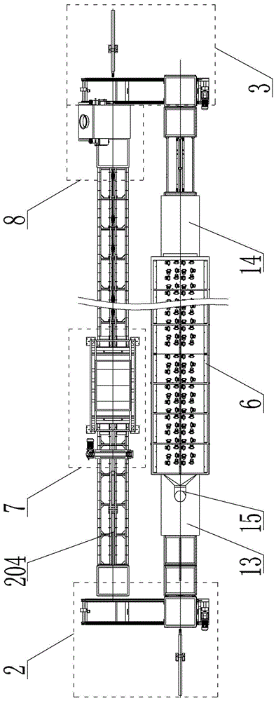
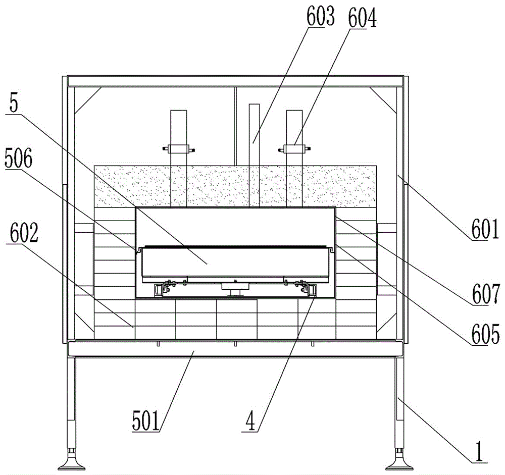
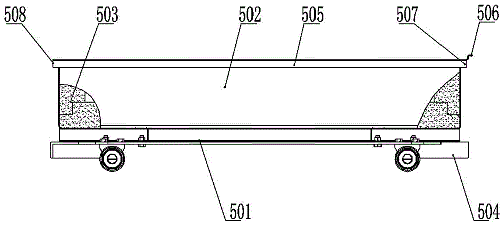
[0040] The specific implementation manners of the present invention will be described in detail below in conjunction with the accompanying drawings.

[0041] see Figure 1-15 , a microwave high-temperature continuous circulation tunnel kiln, comprising two mutually parallel supports 1, an inlet end redirection device 2 and an outlet end redirection device 3 respectively arranged at both ends of the support 1, and a kiln car arranged on the support 1 Walking guide rail 4, kiln car 5, tunnel kiln body 6 arranged on one of the supports 1, feeding device 7 and unloading device 8 arranged on the other support, and the two ends of the tunnel kiln body 6 The feed inlet suppressor 13 and the discharge outlet suppressor 14, the tunnel kiln kiln body 6 includes a shell 601, an insulation layer 602 arranged inside the casing 601, and a microwave resonator set on the inner wall of the insulation layer 602 The cavity 607 , as well as the temperature measuring device 603 and the microwave ...


PUM


Abstract

The invention relates to microwave high-temperature heating equipment, in particular to a microwave high-temperature continuous tunnel kiln. The microwave high-temperature continuous tunnel kiln comprises two bracketsarranged in parallel, an inlet-end turning device and an outlet-end turning devicewhich are arranged at the two end parts of the bracket structure respectively, kiln car traveling guide rails arranged on the brackets, a kiln car, a tunnel kiln body arranged on one bracket, a charging device and a discharging device which are arranged on another bracket, and a feeding hole inhibitor and a discharging hole inhibitor which are arranged at the two end parts of the tunnel kiln body, wherein the tunnel kiln body comprises a housing, a heat preservation layer arranged in the housing, a microwave resonance cavity body formed in the inner wall surface of the heat preservation layer, a temperature measurement device and a microwave source assembly. The microwave high-temperature continuous tunnel kiln has the advantages that the structure is compact, the automation level is high, the heating speed is high, the temperature difference of materials is low, automatic charging, discharging and heating are realized, the working environment is improved, the labor intensity is reduced, the working efficiency is improved, and the continuous material production is achieved.

Description

technical field [0001] The invention relates to microwave high-temperature heating equipment, in particular to a microwave high-temperature continuous circulation tunnel kiln. Background technique [0002] Most of the existing microwave heating equipment is static heating, and it is impossible to realize the tunnel kiln with continuous cycle and non-stop work. For the new structure, it needs a lot of structural innovation and improvement. Orientation, heating, and then complete unloading, such a cyclical process requires a new structure to be designed for a series of specific problems such as kiln cars, tracks, and running mechanisms, and it also needs to be adapted to the new microwave heating and drying form. [0003] Moreover, the traditional microwave heating cavity structure adopts a built-in thermal insulation structure. Although it can achieve good thermal insulation effect, long service life of the reflective surface of the resonant cavity, low working temperature an...

Claims


Application Information

Patent Timeline
Patent Type & Authority Patents(China)
IPC IPC(8): F27B9/06F27B9/26F27B9/34F27B9/38F27B9/39F27B9/40
Inventor 苏建勇张士伟董浩杰
Owner HENAN BODA MICROWAVE EQUIP
Why Eureka
Try Eureka