
Agitation device for concrete for bridge construction

A technology for mixing device and bridge construction, which is applied to cement mixing device, clay preparation device, unloading device, etc., can solve the problems of not being able to perform simultaneously, and that the mixing box cannot be rotated for pouring and mixing.

Active Publication Date: 2018-02-06
顾凯华 +1
View PDF5 Cites 6 Cited by
  • Summary
  • Abstract
  • Description
  • Claims
  • Application Information

AI Technical Summary

Problems solved by technology

[0006] In order to overcome the shortcomings in the prior art that only the stirring rod can rotate, the stirring box cannot rotate, and the pouring and stirring cannot be carried out at the same time, the technical problem to be solved by the present invention is to provide a device that not only can rotate the stirring rod, but also can rotate the stirring box. Concrete mixing equipment for bridge construction that rotates and can be poured and stirred at the same time

Method used


Image

  • Agitation device for concrete for bridge construction
  • Agitation device for concrete for bridge construction
  • Agitation device for concrete for bridge construction

Examples


Embodiment 1

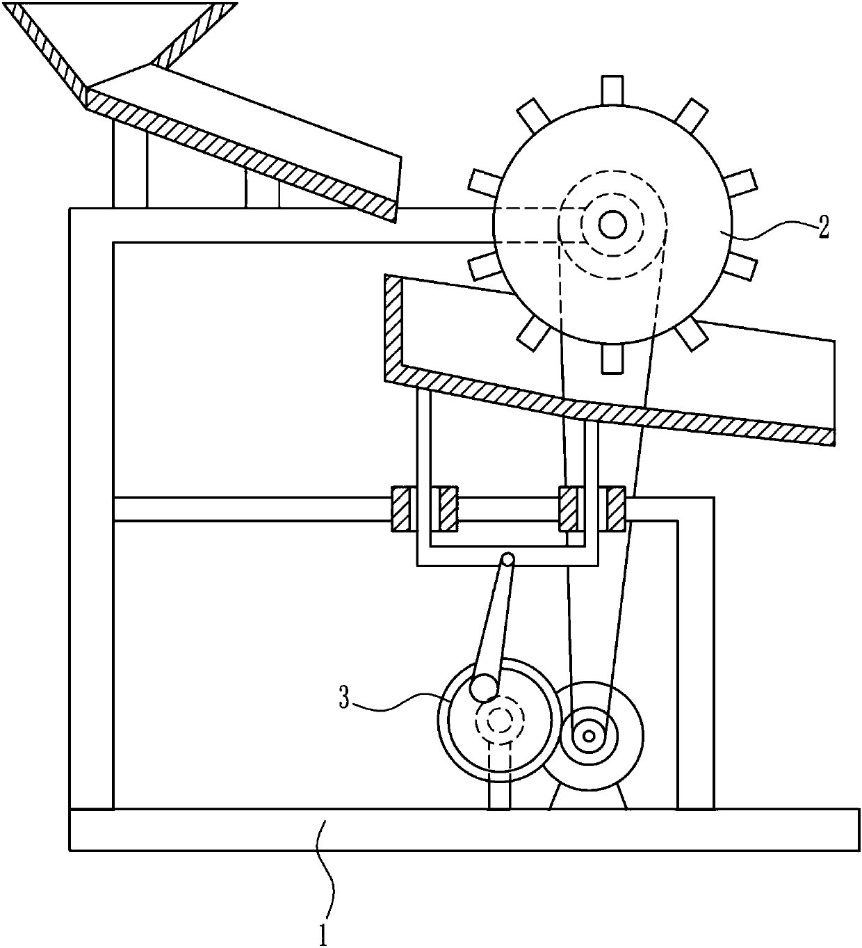
[0034] A bridge construction concrete mixing device, such as Figure 1-7 As shown, it includes a base 1 , a stirring mechanism 2 and a driving mechanism 3 , the stirring mechanism 2 is connected to the top of the base 1 , the driving mechanism 3 is connected to the top of the base 1 , and the stirring mechanism 2 is connected to the driving mechanism 3 .

Embodiment 2

[0036] A bridge construction concrete mixing device, such as Figure 1-7 As shown, it includes a base 1 , a stirring mechanism 2 and a driving mechanism 3 , the stirring mechanism 2 is connected to the top of the base 1 , the driving mechanism 3 is connected to the top of the base 1 , and the stirring mechanism 2 is connected to the driving mechanism 3 .

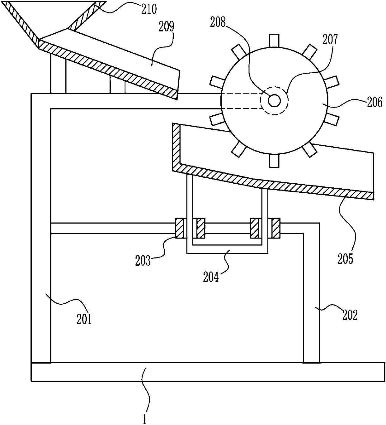
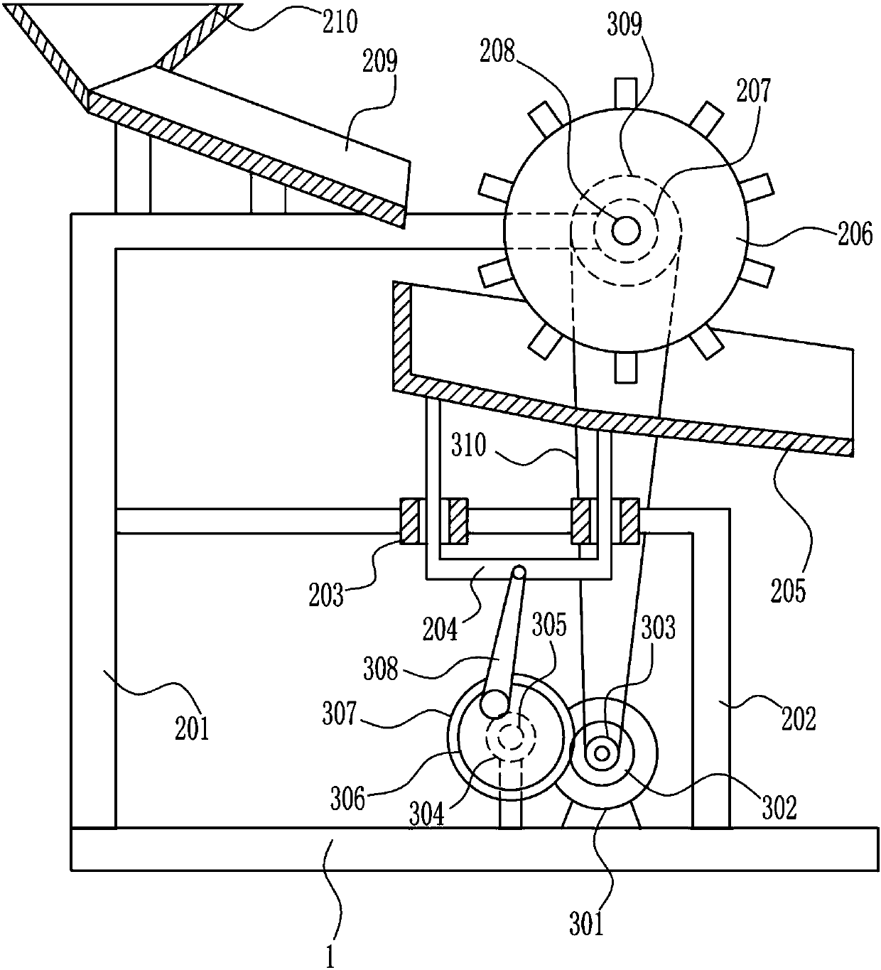
[0037] Stirring mechanism 2 comprises first support 201, second support 202, sliding sleeve 203, slide bar 204, stirring box 205, stirring wheel 206, first bearing seat 207, first rotating rod 208, feed pipe 209 and feeding Bucket 210, the first support 201 is connected to the left side of the top of the base 1, the feed pipe 209 is connected to the left side of the top of the first support 201, the feed hopper 210 is connected to the top of the feed pipe 209, and the first support 201 is connected to the right side. A bearing seat 207, the first bearing seat 207 is connected with the first rotating rod 208, the rear side of...

Embodiment 3

[0039] A bridge construction concrete mixing device, such as Figure 1-7 As shown, it includes a base 1 , a stirring mechanism 2 and a driving mechanism 3 , the stirring mechanism 2 is connected to the top of the base 1 , the driving mechanism 3 is connected to the top of the base 1 , and the stirring mechanism 2 is connected to the driving mechanism 3 .

[0040] Stirring mechanism 2 comprises first support 201, second support 202, sliding sleeve 203, slide bar 204, stirring box 205, stirring wheel 206, first bearing seat 207, first rotating rod 208, feed pipe 209 and feeding Bucket 210, the first support 201 is connected to the left side of the top of the base 1, the feed pipe 209 is connected to the left side of the top of the first support 201, the feed hopper 210 is connected to the top of the feed pipe 209, and the first support 201 is connected to the right side. A bearing seat 207, the first bearing seat 207 is connected with the first rotating rod 208, the rear side of...


PUM


Abstract

The invention relates to an agitation device, and particularly relates to an agitation device for concrete for bridge construction. The invention aims at solving the technical problem of providing anagitation device for the concrete for the bridge construction, in which not only can an agitation rod be rotated but also an agitation box can be rotated and by which the discharging and the agitationcan be further carried out at the same time. In order to solve the technical problem, the invention provides such an agitation device for the concrete for the bridge construction. The agitation device comprises a base and the like, wherein the top of the base is connected with an agitation mechanism; the top of the base is connected with a driving mechanism; the agitation mechanism is connected with the driving mechanism. The invention designs the agitation device for the concrete for the bridge construction; the agitation box can be also powerfully moved up and down while arranged pinion andgearwheel are used for enabling an agitation wheel to agitate the concrete in the agitation box, so that a concrete raw material in the agitation box can be more uniformly agitated and the effects that not only can the agitation rod be rotated and the agitation box can be also rotated but also the discharging and the agitation can be carried out at the same time are realized.

Description

technical field [0001] The invention relates to a stirring device, in particular to a concrete stirring device for bridge construction. Background technique [0002] Bridges generally refer to structures erected on rivers, lakes and seas to allow vehicles and pedestrians to pass smoothly. In order to adapt to the modern high-speed development of the transportation industry, bridges are also extended to buildings that cross mountain streams, poor geology or meet other transportation needs to make traffic more convenient. A bridge is generally composed of a superstructure, a substructure, a support and ancillary structures. The superstructure is also called a bridge span structure, which is the main structure for crossing obstacles; the substructure includes abutments, piers and foundations; Or the force transmission device installed at the supporting place of the bridge abutment; the auxiliary structures refer to the bridge head board, conical slope protection, bank protecti...

Claims


Application Information

Patent Timeline
Patent Type & Authority Applications(China)
IPC IPC(8): B28C5/48B28C5/08B28C7/06B28C7/16
CPCB28C5/0831B28C5/48B28C7/067B28C7/16
Inventor 胡叙成黄建娴汪良伟
Owner 顾凯华
Learn More