Full-automatic de-molding mould for internal thread plastic part

A fully automatic, internal thread technology, applied in the field of injection molding, can solve the problems of bevel gear processing difficulties, large mold volume, and too many cavities, and achieve the effect of saving mold space, low tonnage requirements, and reducing costs

Active Publication Date: 2018-02-06
FUZHOU UNIV +1
View PDF5 Cites 3 Cited by
  • Summary
  • Abstract
  • Description
  • Claims
  • Application Information

AI Technical Summary

Problems solved by technology

The driving device of this utility model is also provided separately from the mould, resulting in a large overall volume of the mould, low equipment manufacturing cost and comprehensive utilization rate
[0005] The common rack and pinion thread stripping mechanism is prone to impact on the rack and pinion during the working process, and is limited by the template, the number of cavities cannot be too many, and bevel gear processing is more difficult
The existing thread automatic demoulding technology mostly uses ejector pins, push blocks or push plates to push out plastic parts, and pulls out the material head with pull hooks. The mold structure is complex and the space cannot be fully utilized.

Method used


Image

  • Full-automatic de-molding mould for internal thread plastic part
  • Full-automatic de-molding mould for internal thread plastic part

Examples


Embodiment Construction

[0020] The technical solutions in the embodiments of the present invention will be clearly and completely described below in conjunction with the accompanying drawings.

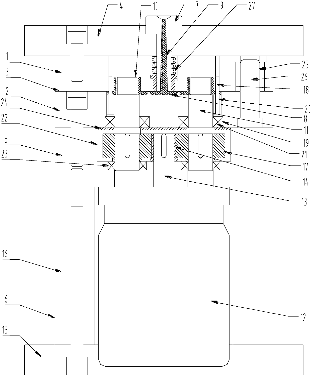
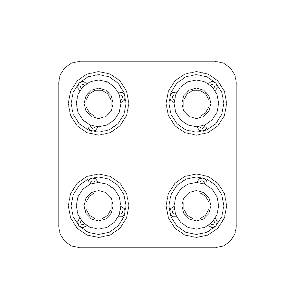
[0021] Such as figure 1 , 2 As shown, a fully automatic demoulding mold for internal threaded plastic parts includes a fixed mold cavity plate 1 and a movable mold cavity plate 2, the fixed mold cavity plate 1 is arranged above the movable mold cavity plate 2, the fixed mold cavity plate 1 and the The parting surface 3 of the plastic part is arranged between the cavity plates 2, the upper end surface of the fixed model cavity plate 1 is provided with a fixed seat plate 4, the lower end surface of the movable model cavity plate 2 is connected to a backing plate 5, and a backing plate 5 is provided below the backing plate 5. There is a movable seat plate 6, the fixed seat plate 4 is fixedly connected with the fixed model cavity plate 1, and the movable model cavity plate 2, backing plate 5, and movable seat pl...


PUM


Abstract

The invention discloses a full-automatic de-molding mould for an internal thread plastic part. The full-automatic de-molding mould comprises a fixed model chamber plate and a moveable model chamber plate, wherein a mold joint of the plastic part is arranged between the fixed model chamber plate and the moveable model chamber plate; a base plate is connected with the lower end face of the moveablemodel chamber plate; a moveable seat plate is arranged under the base plate; a pouring sleeve is arranged at the top end of a fixed seat plate; a main runner is arranged on the mold joint; a product chamber is connected with the main runner; a threaded mold core is arranged in the product chamber; the threaded mold core is penetrated through the moveable seat plate and extends into the base plate;a hydraulic motor is arranged in the moveable seat plate; the lower end of the threaded mold core is connected with the hydraulic motor through a driving mechanism; the threaded mold core is driven by the hydraulic motor to rotate. According to the invention, the hydraulic motor is placed between the base plate and the moveable mold fixing plate, so that the mold space is saved and the requirement for the tonnage of the injection molding machine is lower. A driving gear is adopted for driving a plurality of driven gears to de-mold and the chamber can be fully designed according to the template space. A rotation-stopping mechanism is adopted for guaranteeing the automatic rotation of the plastic part, a spring is adopted for pushing a stub bar and the adjustment and the repairing are convenient.

Description

technical field [0001] The invention relates to the field of injection molding, in particular to a fully automatic demoulding mold for plastic parts with internal threads. Background technique [0002] Mold is an important technological foundation of the manufacturing industry. With the accelerated pace of my country's mold and international standards, and the increasingly intensified market competition, people have put forward higher requirements for the quality, production efficiency and service life of mold injection molding products. In particular, the internal thread spin-off mold is in urgent need of further development and perfection. As an important connection method, threaded connection is widely used in mold injection molding products. The length of core-entry and core-pulling time for internal thread spin-off mold directly affects the production efficiency of the mold. [0003] Patent Publication No. CN104149292A discloses an injection mold structure for rapid ...

Claims


Application Information

Patent Timeline
Patent Type & Authority Applications(China)
IPC IPC(8): B29C45/26B29C45/32B29C45/17
CPCB29C45/1759B29C45/262B29C45/2681B29C45/32
Inventor 郑志敏王乾廷梁卫抗吴世金王建杰张禹黎文峰
Owner FUZHOU UNIV
Why Eureka
Try Eureka