
3D printing equipment for metamaterial preparation

A 3D printing and metamaterial technology, applied in metal processing equipment, 3D object support structure, additive manufacturing, etc., can solve the problems such as preparation methods restricting the development and application of metamaterials, cumbersome preparation process, etc., to ensure the quality and applicability of printed products. A wide range of effects to ensure printing accuracy

Active Publication Date: 2018-02-06
INST OF CHEM CHINESE ACAD OF SCI
View PDF2 Cites 8 Cited by
  • Summary
  • Abstract
  • Description
  • Claims
  • Application Information

AI Technical Summary

Problems solved by technology

However, in view of its complex structure, except that two-dimensional metamaterials can be directly formed by simple methods such as photolithography, the preparation process of three-dimensional metamaterials is extremely cumbersome, and the unit structure needs to be prepared first and built. Method limits the development and application of metamaterials

Method used


Image

  • 3D printing equipment for metamaterial preparation
  • 3D printing equipment for metamaterial preparation
  • 3D printing equipment for metamaterial preparation

Examples


Embodiment 1

[0057] A 40*40cm metal box is used, and the size of the bottom plate is 25*25cm.

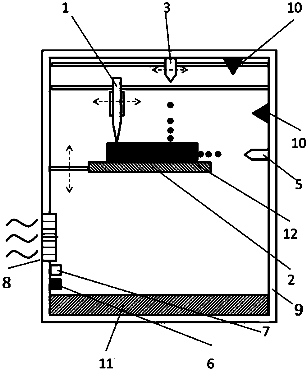
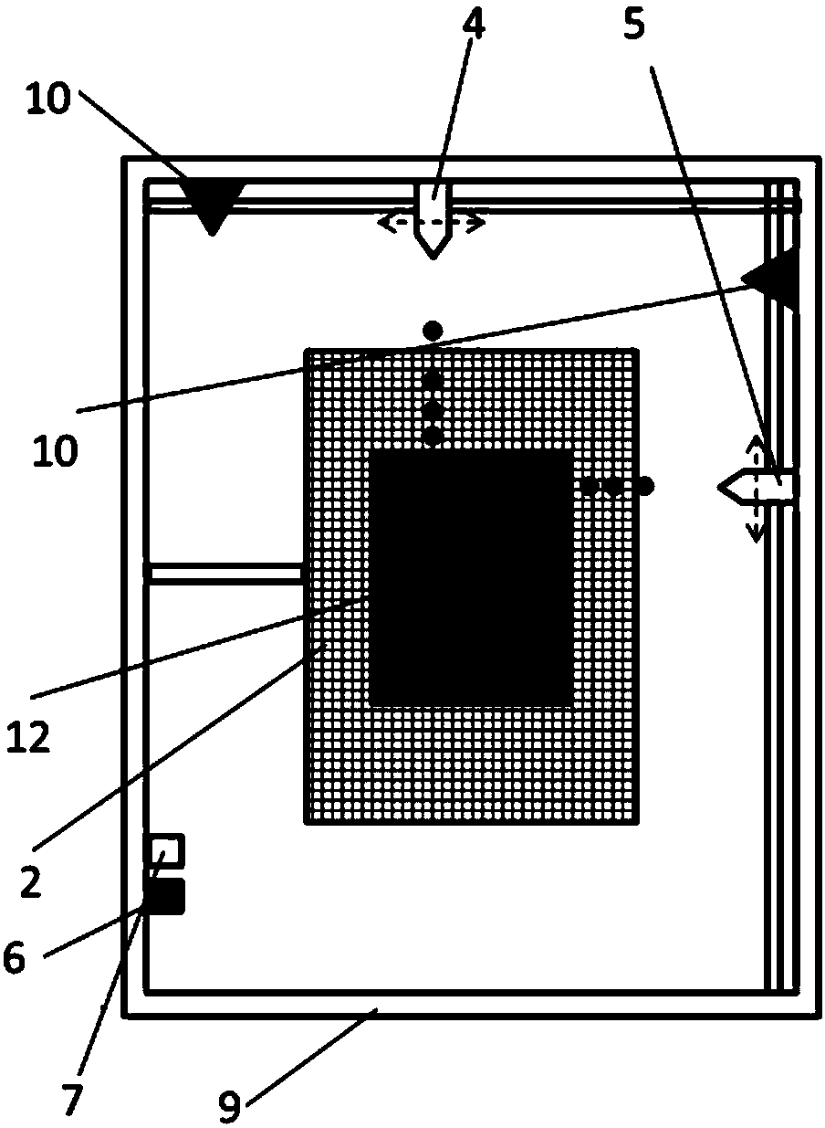
[0058] The substrate deposition system uses the fusion deposition method, adopts a single extrusion needle with a heating jacket, the diameter is 0.5 mm, the deposition temperature is 180 °C, and the deposition material is ABS resin. A single inkjet nozzle with a diameter of 0.3 mm is used, which is arranged in parallel with the extrusion needle, and the two move independently. Silver nanoparticles (average size 100 nm) ink was used. Both the extrusion needle and the inkjet nozzle are driven by two motors, and each moves in the XY plane, while the bottom plate is driven by a single motor, and moves in the Z direction. The temperature of the cabinet is controlled at 50°C and the relative humidity is less than 5%.

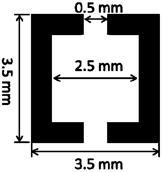
[0059] image 3 The shape shown is a conductive structural unit, the thickness of the unit is 0.2 mm, and the spacing is 1 mm. A two-dimensional metamaterial with a size of 15*15 cm...

Embodiment 2

[0061] It adopts a 40*40cm metal box, and the size of the bottom plate is 25*25cm.

[0062] The substrate deposition system uses the UV curing deposition method, using butyl acrylate as the monomer, the UV initiator is 1173, the nozzle diameter is 0.5 mm, and it moves independently in the XY plane. Use three orthogonal inkjet nozzles with a diameter of 0.3 mm, two of which are located in the XY plane and move independently along the X-axis and Y-axis directions, and the other is located in the positive direction of the Z-axis parallel to the extrusion needle. Independent movement in the XY plane, the bottom plate is driven by a single motor and moves along the Z direction. Silver nanoparticles (average size 100 nm) ink was used. The temperature of the cabinet is controlled at 40°C and the relative humidity is less than 5%.

[0063] Based on a 5*5*2 mm cuboid, with image 3 The shape shown is a conductive structure, which constitutes the structural unit of the metamaterial, ...


PUM


Abstract

The invention relates to 3D printing equipment for metamaterial preparation. The 3D printing equipment comprises a substrate deposition system, a loop deposition system and a pivot control system, wherein the pivot control system controls the substrate deposition system and the loop deposition system; the substrate deposition system is controlled by the pivot control system to construct a substrate of a metamaterial periodical structure; the substrate provides an adhesion site to an electric conducting loop structure; and the loop deposition system is controlled by the pivot control system todeposit electric conducting substances on the substrate, constructed by the substrate deposition system, through an ink jet gun head to form an electromagnetic wave response structure. The 3D printingequipment uses the substrate deposition system and the loop deposition structure for realizing synchronous printing of a substrate material and an electric conducting material to construct a metamaterial with a periodical structure or a similarly periodical structure.

Description

technical field [0001] The invention relates to a supermaterial preparation technology, in particular to a 3D printing device for supermaterial preparation. Background technique [0002] Metamaterials, also known as heterogeneous media, have extraordinary physical properties that natural materials do not possess. Such materials are generally composed of a series of regular arrangements of structural units, which have a periodic structure similar to atoms in crystals, and each structural unit can be understood as an LC loop. As a result, metamaterials resonate with electromagnetic waves of a specific frequency, resulting in unique electromagnetic properties, such as properties such as an apparent negative permittivity (permeability). These characteristics determine that metamaterials have very attractive prospects in imaging, stealth, communication and other fields. [0003] Each structural unit of metamaterials can be regarded as an LC loop, so a specific conductive struct...

Claims


Application Information

Patent Timeline
IPC IPC(8): B29C64/118B22F3/00B33Y30/00B29K55/02B22F12/82
CPCB22F3/00B33Y30/00B29K2055/02B29K2233/08
Inventor 郭靖赵宁徐坚
Owner INST OF CHEM CHINESE ACAD OF SCI
Learn More