Speed regulation magnetic gear for pump

A magnetic gear and speed regulation technology, applied in permanent magnet clutches/brakes, electrical components, electromechanical devices, etc., can solve the problems of limiting the lift and flow of the drive pump, unable to cover the speed range, long continuous working time, etc. Speed, good working environment, no corrosion effect

Pending Publication Date: 2018-02-06
深圳市泉胜新技术开发有限公司
View PDF5 Cites 1 Cited by
  • Summary
  • Abstract
  • Description
  • Claims
  • Application Information

AI Technical Summary

Problems solved by technology

Although its efficiency cannot compare with DC brushless motors, because of its simple structure, no need to drive, and the advantages of being directly connected to the grid, it has the characteristics of high reliability and long continuous working time, and it still has great advantages in some places that require continuous work. The advantages
However, the transmission ratio of the traditional magnetic gear is fixed at 1:1, and the speed is directly controlled by the driving motor, while the rated speed of the motor (AC asynchronous motor) is restricted by the frequency of the grid, which cannot cover a higher speed range, thus limiting the driven pump. Head and Flow
[0003] In summary, the magnetic gear has the problem of inconvenience in practice, so it is necessary to improve it

Method used


Image

  • Speed regulation magnetic gear for pump
  • Speed regulation magnetic gear for pump
  • Speed regulation magnetic gear for pump

Examples


Embodiment Construction

[0028] The present invention will be described in detail below in conjunction with the accompanying drawings and specific embodiments.

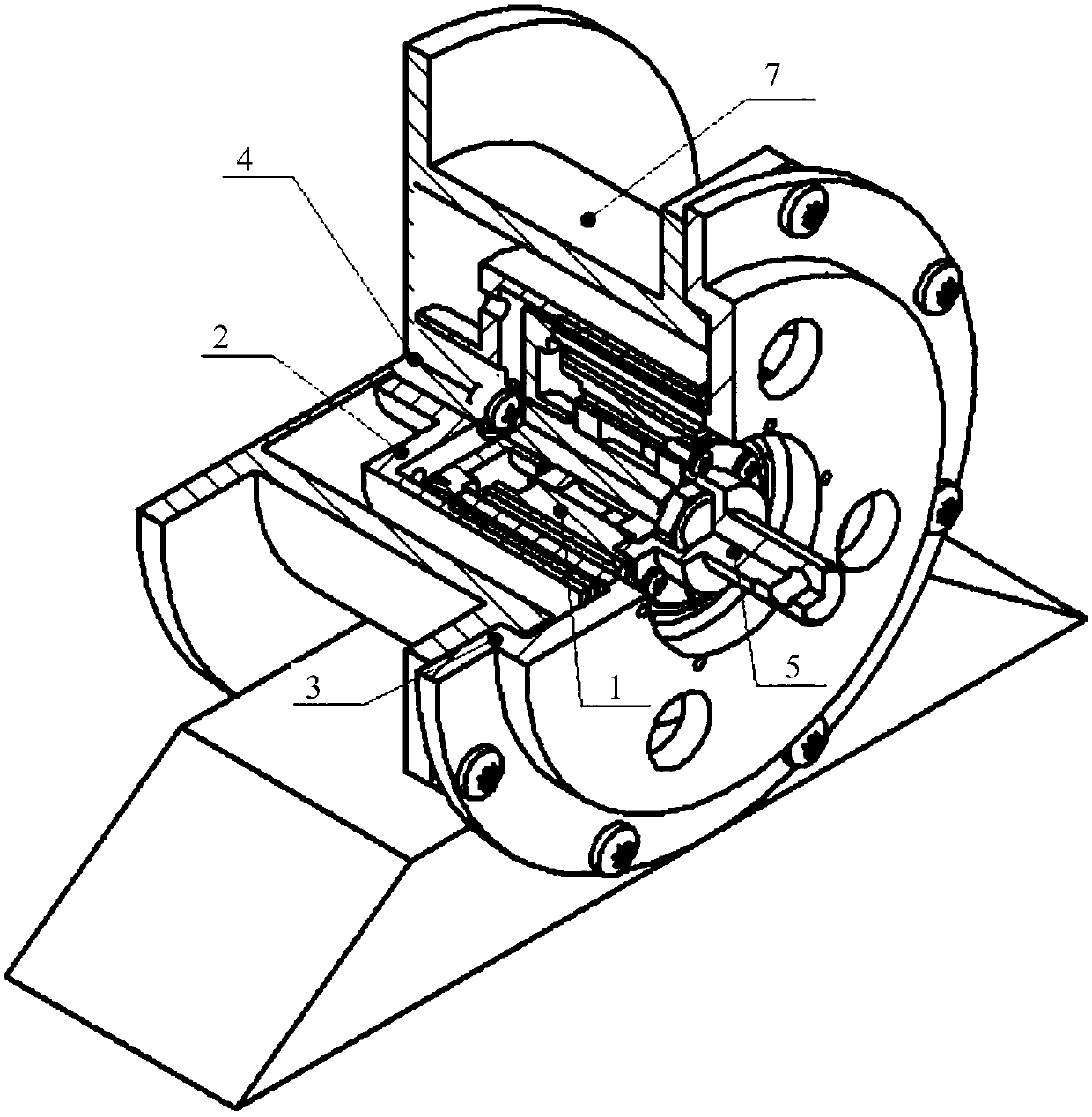
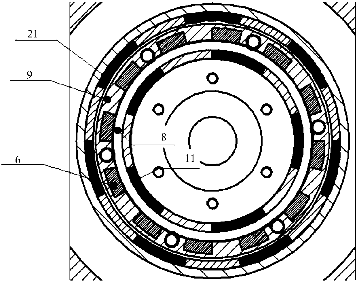
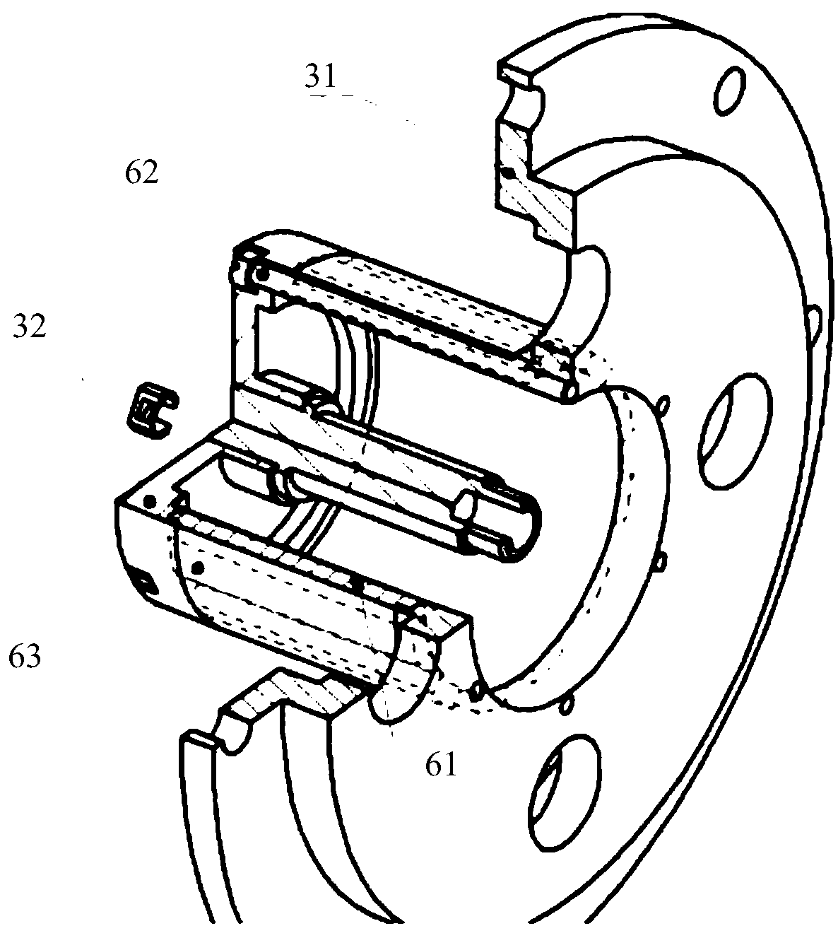
[0029] refer to Figures 1 to 3 As shown, the present invention provides a speed-regulating magnetic gear for pumps, including an inner rotor 1, an outer rotor 2, a spacer 3, an input shaft 4, an output shaft 5, and a magnetic ring 6; the spacer 3 includes a first end Cover 31, second end cap 32; the cross-section of the spacer 3 is a T-shaped structure, its transverse end is a disc-shaped first end cap 31, the vertical end is a hollow cylinder, and the vertical end is engaged with The second end cover 32; the magnetic adjustment ring 6 is potted on the vertical end of the spacer sleeve 3 through the potting glue 63, and its two ends are respectively inserted into the first end cover 31 and the second end cover 32; the input shaft 4, output The shaft 5 is respectively connected to one end of the outer rotor 2 and one end of the inner rotor 1...


PUM


Abstract

The invention discloses a speed regulation magnetic gear for a pump. The gear comprises an inner rotor, an outer rotor, an isolation sleeve, an input shaft, an output shaft and a magnetism adjusting ring. The isolation sleeve comprises a first end cover and a second end cover. The cross section of the isolation sleeve is of a T-type structure and the transverse end of the isolation sleeve is the disc-shaped first end cover. The vertical end is in a shape of a hollow cylinder. The second end cover is clamped to the end part of the vertical end. The magnetism adjusting ring is encapsulated to the vertical end of the isolation sleeve through encapsulation glue. Two ends of the magnetism adjusting ring are inserted into the first end cover and the second end cover. The input shaft and the output shaft are connected to one end of the outer rotor and one end of the inner rotor. The other end of the inner rotor, the T-type vertical end of the isolation sleeve and the other end of the outer rotor are successively nested from the interior to the exterior. According to the invention, through optimized design, the invention provides the magnetic gear with adjustable speed under the conditionof not changing the structure of a pump body; under the premise that the reliability and the continuous working time are not reduced, the rotation speed range of impellers is effectively expanded; thelife and the flows of the pump are changed and the application prospects of the pump are extended.

Description

technical field [0001] The invention relates to the technical field of industrial motors, in particular to a speed-regulating magnetic gear for pumps. Background technique [0002] At present, the mainstream of driving motors for industrial pumps is still AC asynchronous motors, which transmit power to the impeller of the pump through a set of magnetic gears. Although its efficiency cannot compare with DC brushless motors, because of its simple structure, no need to drive, and the advantages of being directly connected to the grid, it has the characteristics of high reliability and long continuous working time, and it still has great advantages in some places that require continuous work. The advantages. However, the transmission ratio of the traditional magnetic gear is fixed at 1:1, and the speed is directly controlled by the driving motor, while the rated speed of the motor (AC asynchronous motor) is restricted by the frequency of the grid, which cannot cover a higher sp...

Claims


Application Information

Patent Timeline
Patent Type & Authority Applications(China)
IPC IPC(8): H02K49/10
CPCH02K49/102H02K49/106
Inventor 彭勇林文泉易宇赵凌锋
Owner 深圳市泉胜新技术开发有限公司
Why Eureka
Try Eureka