Power control method and system and optical line terminal and optical network unit

A technology for optical network units and optical line terminals, applied in transmission systems, electromagnetic wave transmission systems, electrical components, etc., can solve problems such as difficulty and OLT misjudgment, and achieve the goal of improving accuracy, improving misjudgment problems, and reducing implementation difficulty Effect

Active Publication Date: 2020-02-14
CHINA TELECOM CORP LTD
View PDF6 Cites 0 Cited by
  • Summary
  • Abstract
  • Description
  • Claims
  • Application Information

AI Technical Summary

Problems solved by technology

This will bring higher difficulty to the signal judgment on the OLT side, making the OLT prone to signal misjudgment

Method used


Image

  • Power control method and system and optical line terminal and optical network unit
  • Power control method and system and optical line terminal and optical network unit
  • Power control method and system and optical line terminal and optical network unit

Examples


Embodiment Construction

[0030] The following will clearly and completely describe the technical solutions in the embodiments of the present invention with reference to the accompanying drawings in the embodiments of the present invention. Obviously, the described embodiments are only some, not all, embodiments of the present invention. The following description of at least one exemplary embodiment is merely illustrative in nature and in no way taken as limiting the invention, its application or uses. Based on the embodiments of the present invention, all other embodiments obtained by persons of ordinary skill in the art without making creative efforts belong to the protection scope of the present invention.

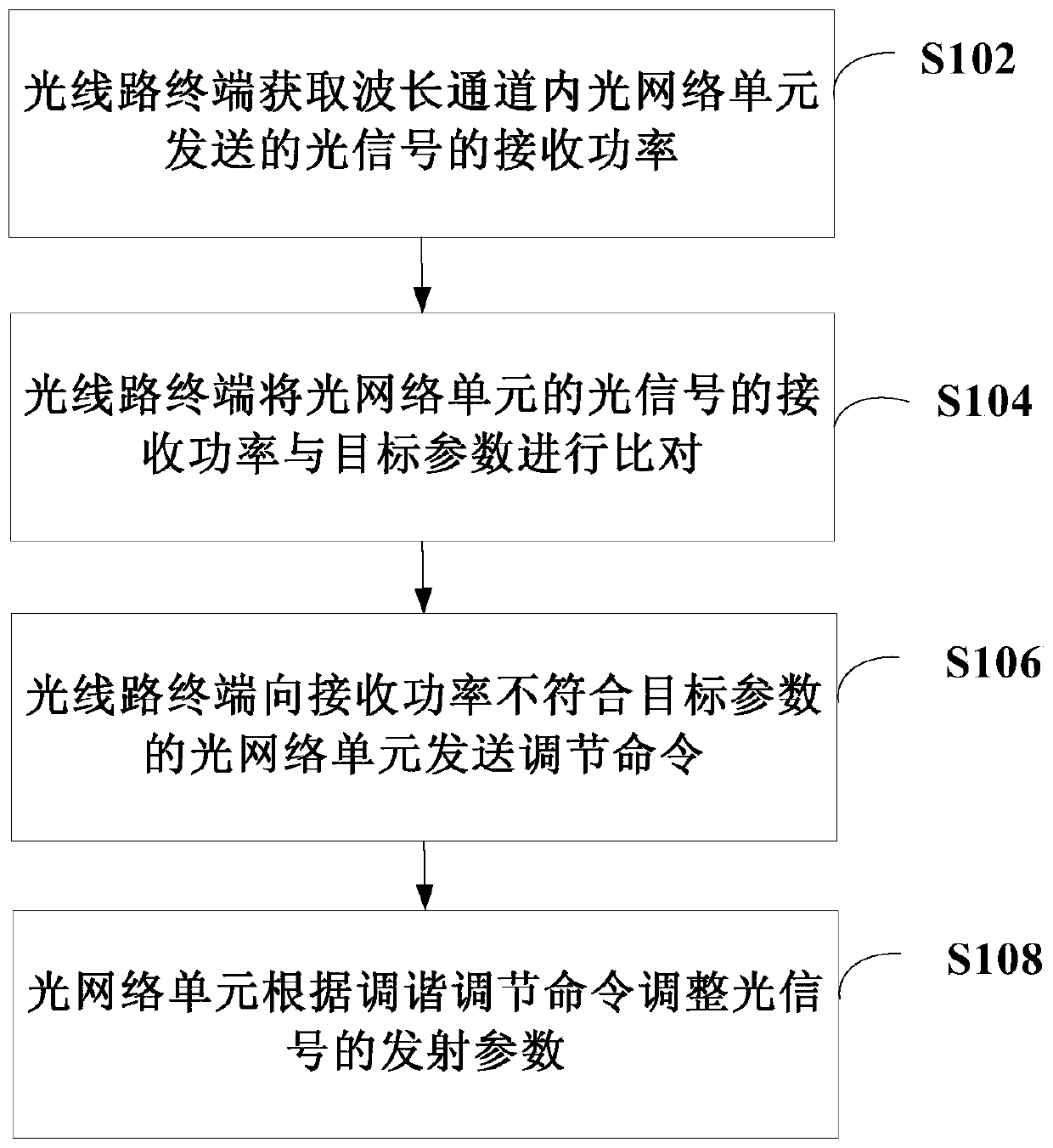
[0031] The invention proposes a new power control method in the passive optical network to ensure the accuracy of the judgment of the optical line terminal on the received signal of the optical network unit.

[0032] The following reference Figure 1 to Figure 4 The method of power control of t...


PUM


Abstract

The invention discloses a power control method and system, an optical line terminal and an optical network unit, and relates to the technical field of optical fiber communication. The method includes:the optical line terminal obtains a receiving power of an optical signal sent by the optical network unit in a wavelength channel, compares the receiving power of the optical signal of the optical network unit and a target parameter, and sends an adjusting command to the optical network unit whose receiving power is not in accordance with the target parameter; and the optical network unit adjustsan emission parameter of the optical signal according to the adjusting command. According to the method and system, the optical network unit is controlled to adjust the emission parameter through theoptical line terminal, the power of the optical signal of each optical network unit received by the optical line terminal can be maintained in a certain intensity range, the problem of misjudgment due to different intensities of receiving signals is improved, and the accuracy of the judgment of the receiving signals by the optical line terminal is improved; besides, the side of the optical line terminal no longer needs an automatic gain control function so that the realization difficulty for receiving hardware by the optical line terminal is reduced.

Description

technical field [0001] The invention relates to the technical field of optical fiber communication, in particular to a power control method and system, an optical line terminal and an optical network unit. Background technique [0002] Deployment and application of passive optical network (Passive Optical Network, PON) technology in the current network, a passive optical network includes an optical line terminal (Optical Line Terminal, OLT) installed in the central control station, and a batch of supporting equipment installed in the Optical Network Unit (ONU) at the user site. In the process of uplink communication, due to the location of each ONU and the different external environment, the optical signal of each ONU received by the OLT side may be strong or weak. This will bring higher difficulty to the signal judgment on the OLT side, making it easy for the OLT to generate misjudgment of signals. [0003] For the above problems, the existing solution is that in the tech...

Claims


Application Information

Patent Timeline
Patent Type & Authority Patents(China)
IPC IPC(8): H04B10/564H04B10/572H04B10/079
CPCH04B10/07955H04B10/564H04B10/572
Inventor 张德智
Owner CHINA TELECOM CORP LTD
Why Eureka
Try Eureka