Paper shredding device with high stability

A high-stability, paper-shredding technology, applied to mixers with rotating stirring devices, transportation, packaging, and dissolution, can solve the problems of different time and energy, easy to be bumped or overturned, and inconvenient to use, etc., to achieve The effect of improving security function, improving stability, and improving convenience

Inactive Publication Date: 2018-02-09
四川首翔智宇科技有限公司
View PDF0 Cites 2 Cited by
  • Summary
  • Abstract
  • Description
  • Claims
  • Application Information

AI Technical Summary

Problems solved by technology

[0003] The technical problem to be solved by the present invention is that the existing paper shredders can shred paper into very small paper, but the paper can still be spliced ​​to obtain the above information. The difference is that the time and energy required for splicing are different. That's all, so it still can't achieve complete confidentiality, and there is a great risk of leakage, and the existing shredders need to hold the paper by hand until it is completely shredded when it is used. It is very inconvenient, and at the same time, paper shredders are usually placed directly on the place, the stability is not high, and it is easy to be bumped or overturned. The purpose is to provide a document shredding device with high stability. After being granulated or foamy, the waste debris is put into water and stirred to make it into pulp, so that the ink on the paper will also fall off and disappear due to soaking in water, so that even if someone gets the pulp, it is completely It is impossible to restore the information on the paper, which greatly improves the confidentiality function and makes the function of shredding more thorough. At the same time, when shredding, there is no need to hold it manually, and it can automatically transfer the paper to be shredded. , and improve the stability of the shredder, it is not easy to fall over when it is bumped

Method used


Image

  • Paper shredding device with high stability

Examples


Embodiment

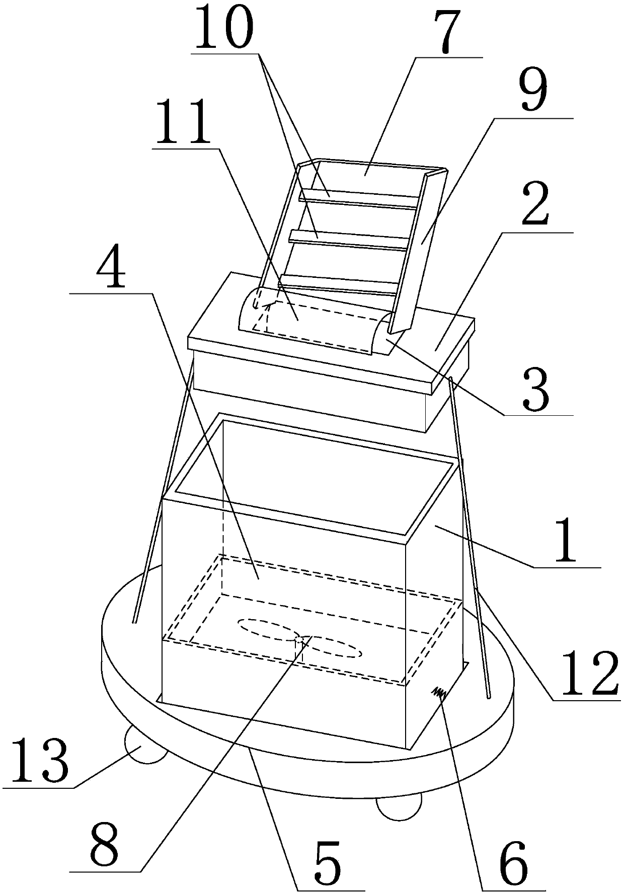
[0023] Such as figure 1 As shown, the document shredding device with high stability of the present invention includes a waste bin 1 and a machine cover 2 installed on the waste bin 1. The machine cover 2 is provided with a paper inlet 3 for putting paper to be shredded. Below the paper inlet 3 in the cover 2, there is a cutting knife with a knife tip, which cuts the paper under the drive of the motor; The stirring paddle 8 is filled with water, the bottom of the waste bucket 1 is provided with a cylindrical fixed base 5, the fixed base 5 is provided with a placement groove, the waste bucket 1 is arranged in the placement groove, and the outer wall of the waste bucket 1 is in contact with the The inwalls of the placement grooves are connected by shock-absorbing springs 6, and the both sides of the waste bin 1 on the fixed base 5 are respectively provided with support rods 12 which are arranged obliquely, and the tops of the support rods 12 are connected with the side walls of t...


PUM


Abstract

Disclosed is a paper shredding device with high stability. The paper shredding device with high stability comprises a waste material barrel and a machine cover. A paper inlet is formed in the machinecover. A shredded paper pool is arranged at the bottom of the waste material barrel, and stirring paddles are arranged in the shredded paper pool. A fixing base is arranged at the bottom of the wastematerial barrel in a sleeving mode, the waste material barrel and a placement groove are connected through a damping spring, supporting rods are arranged on the two sides of the waste material barrel,and the top ends of the supporting rods are connected with the side wall of the fixing base. A paper feeding plate is arranged on the machine cover, limiting plates are arranged on the two sides of the paper feeding plate, and baffles are arranged between the limiting plates. By the adoption of the efficient paper shredding device, after paper is shredded to form particles or powder, waste scrapsare put into water to be stirred and broken, so that paper pulp is formed. In this way, ink marks on the paper can fall off and disappear due to the fact that the paper is soaked in the water, information on the paper cannot be recovered even though persons get the paper pulp, and the secrecy function is greatly improved. Meanwhile, conveying of paper to be shredded can be automatically conducted, and the stability is improved.

Description

technical field [0001] The invention relates to a paper shredder, in particular to a file shredding device with high stability. Background technique [0002] A paper shredder is a machine used to shred and destroy paper. In order to achieve the purpose of keeping the discarded documents confidential, the paper should be divided into many small pieces of paper. A shredder consists of a set of rotating blades, a comb and a drive motor. The paper is fed from the middle of the interlocking blades and is divided into many small pieces of paper to achieve the purpose of confidentiality. The shredding method refers to the shape of paper shredded by a shredder knife after being processed by a shredder. According to the composition mode of paper shredder knife, existing paper shredding mode has: shredded shape, section shape, foam shape, strip shape, granular shape, silk shape etc. If it is a general office occasion, choose granular, filamentary, segmental, and strip-like ones. T...

Claims


Application Information

Patent Timeline
Patent Type & Authority Applications(China)
IPC IPC(8): B02C18/12B02C18/16B02C18/22B01F7/16
CPCB02C18/0007B02C18/12B02C18/16B02C18/2241B01F27/808
Inventor 刘洪军
Owner 四川首翔智宇科技有限公司
Why Eureka
Try Eureka