Electric brake booster for automobile

An electric brake and booster technology, applied in the direction of brakes, brake transmission devices, hydraulic brake transmission devices, etc., can solve the problem that the vacuum booster cannot brake automatically.

Pending Publication Date: 2018-02-09
上海拿森汽车电子有限公司
View PDF0 Cites 12 Cited by
  • Summary
  • Abstract
  • Description
  • Claims
  • Application Information

AI Technical Summary

Problems solved by technology

[0005] The purpose of the present invention is to provide an electric brake booster for automobiles to solve the technical problem that the vacuum booster cannot brake automatically in the prior art

Method used


Image

  • Electric brake booster for automobile
  • Electric brake booster for automobile

Examples


Embodiment Construction

[0039] The technical solutions of the present invention will be further described below in conjunction with the accompanying drawings and embodiments. It should be understood that the specific embodiments described here are only used to explain the present invention, but not to limit the present invention. In addition, it should be noted that, for the convenience of description, only the parts related to the present invention are shown in the drawings but not all of them.

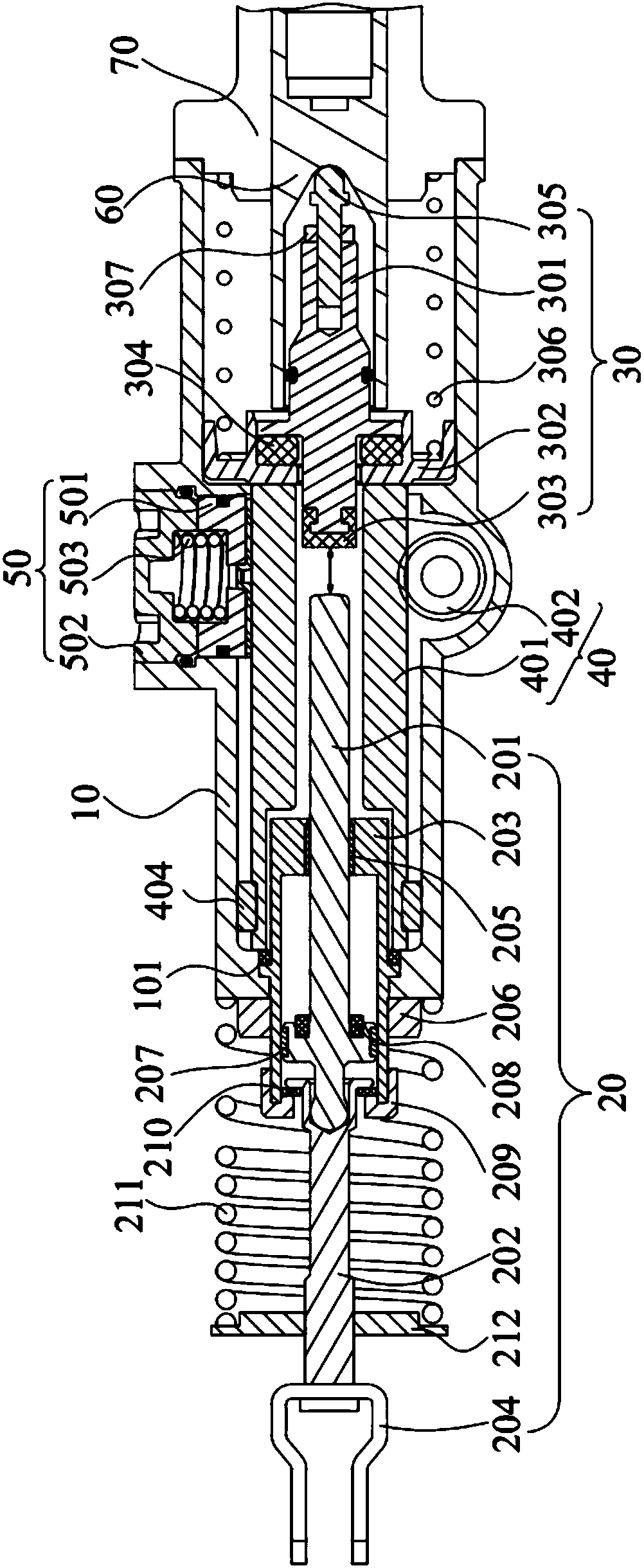
[0040] see figure 1 , an electric brake booster for automobiles, including a housing 10, a push rod assembly 30 and a push rod assembly 20 installed in the housing 10, and the various components and their usage methods are described in detail below.

[0041] Push rod assembly 20 comprises push rod 201, push rod seat 202 and steel sleeve 203, and one end of push rod 201 is connected with pedal (not shown in the figure) through push rod seat 202, and the other end of push rod 201 is connected with push rod a...


PUM


Abstract

The invention discloses an electric brake booster for automobiles, which comprises a casing, a push rod assembly and a push rod assembly installed in the casing; the push rod assembly includes a push rod, one end of the push rod is connected with a pedal, and the push rod There is a decoupling gap between the other end and the ejector rod assembly; the ejector rod assembly includes the ejector rod, one end of the ejector rod is connected to the driving mechanism, and the other end of the ejector rod is connected to the master cylinder piston; when the driver depresses the pedal, the driving mechanism After receiving the signal, the ejector rod is driven to push the piston of the master cylinder to achieve braking. At the same time, the push rod moves in a straight line under the push of the pedal. Due to the decoupling gap between the push rod and the ejector rod assembly, the push rod will not push against the ejector rod assembly. ; When the electronic control system fails, the driving mechanism will not start. After the pedal drives the push rod to eliminate the decoupling gap, the push rod pushes to the ejector rod assembly, and the force of the driver's stepping on the pedal pushes the master cylinder piston to realize the electronic control failure. brake.

Description

technical field [0001] The invention relates to the technical field of automobiles, in particular to an electric brake booster for automobiles and a control method thereof. Background technique [0002] With the improvement of the country's consumption level, cars have accelerated into ordinary families, and more and more consumers have put forward higher and higher requirements for the comfort, safety and economy of cars. With the gradual improvement of automatic parking and braking driving technology, more and more consumers will choose this kind of comfort configuration. These two functions must require that the car can realize automatic braking. Automatic emergency braking system has become a major The key research and development project of the car factory. [0003] Most of the traditional car braking systems use vacuum booster. The vacuum booster uses vacuum (negative pressure) to increase the force exerted by the driver on the pedal. As long as you step on the pedal ...

Claims


Application Information

Patent Timeline
Patent Type & Authority Applications(China)
IPC IPC(8): B60T13/74B60T13/565
CPCB60T13/745B60T13/565
Inventor 于鑫
Owner 上海拿森汽车电子有限公司
Why Eureka
Try Eureka