
Underwater pier pouring machine

A pouring machine and bridge pier technology, which is applied in the field of bridges and construction, can solve the problems of unstable placement of bridge piers and short service life of bridges, and achieve the effect of improving pouring efficiency and quality.

Active Publication Date: 2018-02-09
四川域高建筑工程有限公司
View PDF5 Cites 6 Cited by
  • Summary
  • Abstract
  • Description
  • Claims
  • Application Information

AI Technical Summary

Problems solved by technology

[0002] In the construction of underwater bridge piers, the built bridge piers are usually placed underwater. Since the underwater piers are not tightly combined with the underwater soil, it is easy to cause unstable placement of the bridge piers and short service life of the bridge. Therefore, it is urgently needed. A machine that builds bridge piers underwater

Method used


Image

  • Underwater pier pouring machine
  • Underwater pier pouring machine
  • Underwater pier pouring machine

Examples


Embodiment Construction

[0020] The technical solutions of the present invention will be further specifically described below through the embodiments and in conjunction with the accompanying drawings.

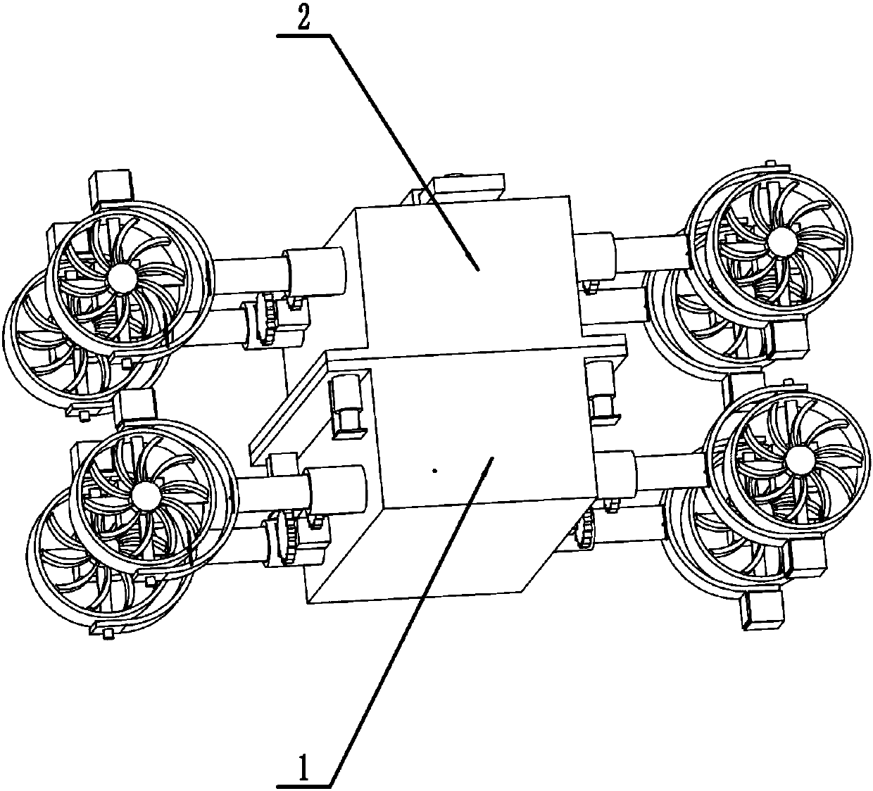
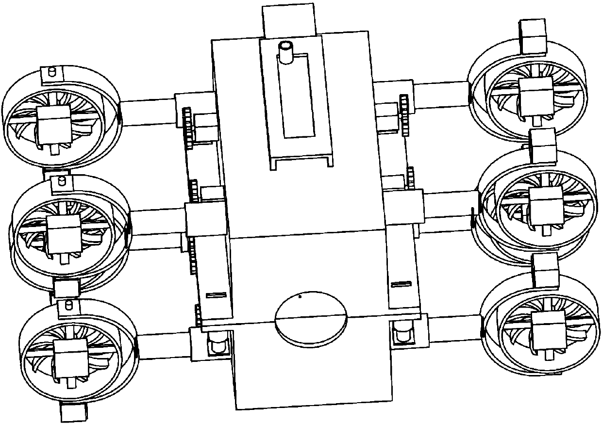
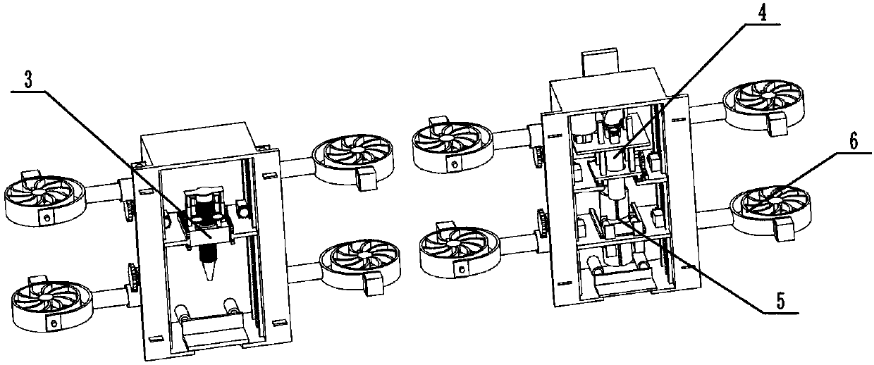
[0021] Example figure 1 , figure 2 , image 3 , Figure 4 , Figure 5 , Figure 6 , Figure 7 , Figure 8 , Figure 9 , Figure 10 , Figure 11 , Figure 12 , Figure 13 , Figure 14 , Figure 15 , Figure 16 , Figure 17 , Figure 18 , Figure 19 Shown, a kind of underwater pier pouring machine, comprises first housing part 1, second housing part 2, drilling part 3, pouring part 4, support pipe part 5, eight turbine parts 6, it is characterized in that: described The four second L-shaped plates 109 of the first housing part 1 are respectively slidably installed in the four first rectangular grooves 210 of the second housing part 2; the four first dovetail grooves 304 of the drilling part 3 are respectively Slidingly installed on the four first positioning blocks 106 inside the first...


PUM


Abstract

The invention discloses a pier pouring machine which comprises a first shell portion, a second shell portion, a borehole portion, a pouring portion, a supporting tube portion, and eight turbine portions. The pier pouring machine is characterized in that four second L-shaped plates of the first shell portion are respectively slidably installed in the four first rectangular grooves of the second shell portion. A ninth step motor drives an eighth gear to rotate and the rotation of the eighth gear further drives a ninth gear to rotate and a first connecting tube to rotate 90 degrees so that the first connecting tube and the second connecting pipe are connected and discharged through a third connecting tube. Then the ninth step motor drives the eighth gear to rotate and the rotation of the eighth gear further drives the ninth gear to rotate and the first connecting tube to rotate 90 degrees so that the first connecting tube is connected with the connecting tube on the side surface of a stirring barrel. An eighth step motor drives a stirring wheel to stir the cement and pour the cement into a prepared hole. The underwater pier pouring machine achieves automated suction of the water fromthe hole and automated pouring of the cement into the hole, realizes automated pouring of the bridge pier and the improvement of the pouring efficiency and quality of the pier.

Description

technical field [0001] The invention relates to the technical field of bridges and buildings, in particular to an underwater pier pouring machine. Background technique [0002] In the construction of underwater bridge piers, the built bridge piers are usually placed underwater. Since the underwater piers are not tightly combined with the underwater soil, it is easy to cause unstable placement of the bridge piers and short service life of the bridge. Therefore, it is urgently needed. A machine that can complete the construction of bridge piers underwater. Contents of the invention [0003] In view of the above problems, the present invention provides an underwater pier pouring machine, in which the ninth stepping motor drives the eighth gear and then drives the ninth gear to drive the first connecting pipe to rotate 90 degrees so that the first connecting pipe is connected to the second connecting pipe , through the tenth stepping motor to drive the water pump to suck up t...

Claims


Application Information

Patent Timeline
Patent Type & Authority Applications(China)
IPC IPC(8): E01D21/00E02D15/06
CPCE01D21/00E02D15/06
Inventor 吴利伟
Owner 四川域高建筑工程有限公司
Learn More