
Fireproof window

A fire-proof window, a pair of technology, applied in the field of fire-proof windows, can solve the problems that the structural strength and thermal insulation performance of the fire-proof windows cannot be taken into account at the same time, and achieve the effects of convenient disassembly and assembly, strong structural strength, and strong fireproof performance

Pending Publication Date: 2018-02-09
SUZHOU KELIDA BUILDING & DECORATION CO LTD
View PDF6 Cites 1 Cited by
  • Summary
  • Abstract
  • Description
  • Claims
  • Application Information

AI Technical Summary

Problems solved by technology

[0003] The main purpose of the present invention is to provide a fireproof window to solve the problem that the structural strength and thermal insulation performance of the fireproof window in the prior art cannot be taken into account at the same time

Method used


Image

  • Fireproof window
  • Fireproof window
  • Fireproof window

Examples


Embodiment 1

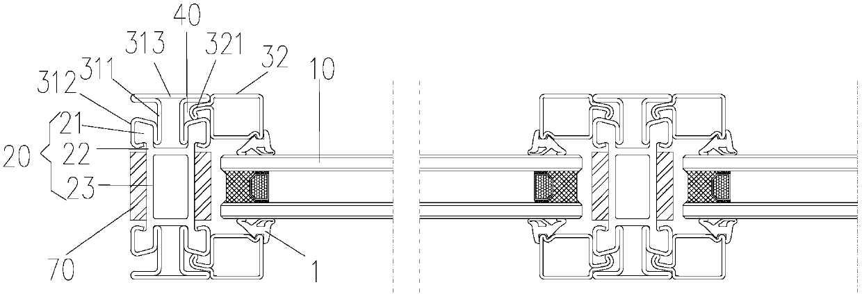
[0025] like figure 1 As shown, the fireproof window of Embodiment 1 includes: a glass panel 10, a fireproof member 20, a first fixing structure and a second fixing structure, the fireproof member 20 is arranged on the outside of one end of the glass panel along its extending direction, and the first fixing structure The second fixing structure and the second fixing structure are respectively installed on opposite sides of the fireproof member 20. The first fixing structure has a first pressing part extending along the extending direction of the glass panel 10, and the second fixing structure has a pressing part extending along the extending direction of the glass panel 10. The second pressing part of the first pressing part is formed between the first pressing part and the second pressing part for installing one end of the glass panel 10 . The fireproof member 20 fixes the glass panel 10 through the first fixing structure and the second fixing structure, which enhances the str...

Embodiment 2

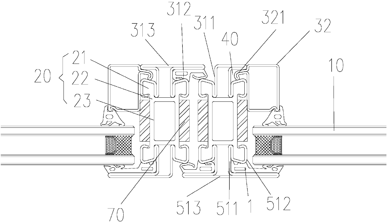
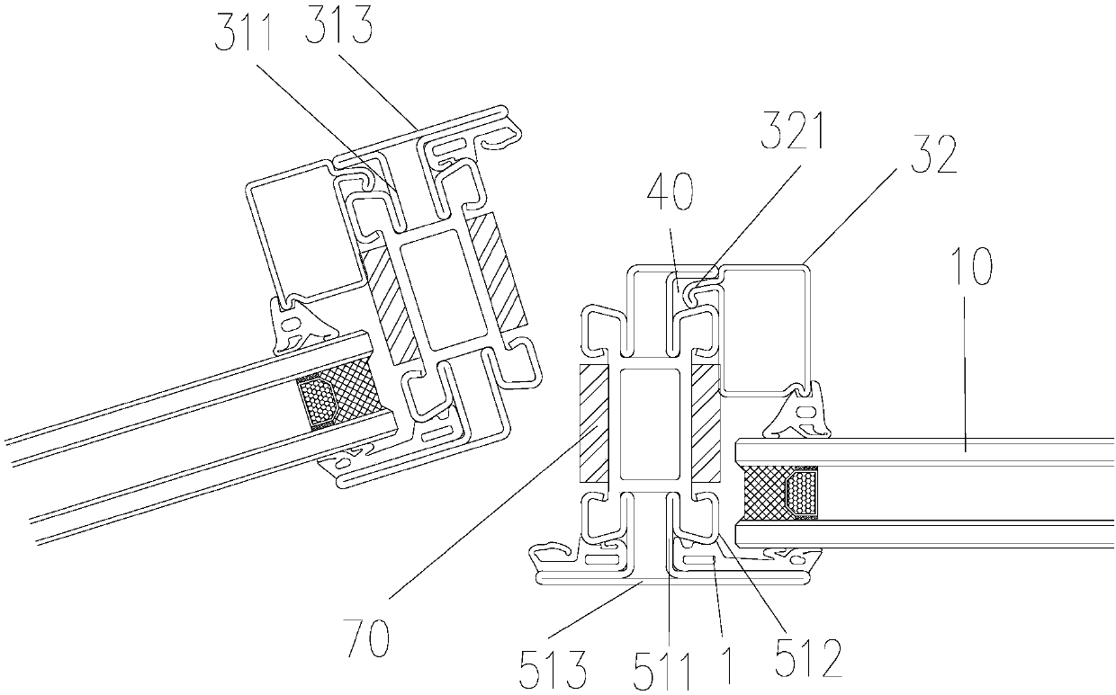
[0037] figure 2 and image 3 The structure of Embodiment 2 showing the structure of the fireproof window of the present invention, Figure 4 It is the structure of the first fan frame of the second embodiment. The difference between the structure of the fire window of the second embodiment and the first fan is that the shape of the first fan frame is different from that of the second fixed structure. In the second embodiment, one side of the second straight long piece 313 of the first fan frame is bent 180 degrees and then connected to the side of the first straight long piece 311 away from the fireproof member 20, and the second straight long piece 313 The other side is connected to the side of the other first straight piece 311 away from the fireproof member 20, and the overlapping part of the second straight piece 313 and the adjacent first bent piece 312 are formed for clamping the first The first locking groove 40 of the glass pressure wire 32 and the prevention of the...


PUM


Abstract

The invention provides a fireproof window. The fireproof window comprises a glass panel, a fireproof piece, a first fixed structure and a second fixed structure; the fireproof piece is arranged on theouter side of one end of the glass panel in the extending direction of the glass panel, and the first fixed structure and the second fixed structure are correspondingly installed on the two oppositesides of the fireproof piece; the first fixed structure is provided with a first pressing part extending in the extending direction of the glass panel, and the second fixed structure is provided witha second pressing part extending in the extending direction of the glass panel; and an installing groove opening which is used for installing of one end of the glass panel is formed between the firstpressing part and the second pressing part. According to the technical scheme of the fireproof window, the defect that the structure strength and thermal insulation performance of an existing fireproof window cannot be simultaneously taken into account is overcome.

Description

technical field [0001] The invention relates to the technical field of buildings, in particular to a fireproof window. Background technique [0002] In architectural design, it is usually necessary to set fire protection for buildings. Setting fire-proof materials or fire-proof devices in buildings can effectively prevent fire from spreading, thereby ensuring personal safety and property safety. Fire-proof windows are fire-proof devices with fire-proof functions. There are mainly three kinds of fireproof windows in the existing technology: the first type of fireproof window is based on aluminum alloy, and fire-resistant and flame-retardant materials are added to the aluminum alloy material to meet the fireproof requirements; the second type of fireproof window is mainly made of steel. The melting point is high so that it can realize the fireproof function; the third type of fireproof window uses a new type of glass fiber reinforced polyurethane material as the main material,...

Claims


Application Information

Patent Timeline
IPC IPC(8): E06B5/16E06B3/58E06B3/66E06B3/14E06B7/16
CPCE06B3/12E06B3/58E06B3/66E06B5/164E06B5/165
Inventor 刘电张栋梁周兰兰
Owner SUZHOU KELIDA BUILDING & DECORATION CO LTD
Learn More