Dynamic balance machining die, adjusting method and operating method

A technology for processing molds and moving molds, applied in the field of dynamic balancing processing molds and adjustment, can solve the problems of unbalanced fans, difficult to ensure accuracy, low processing efficiency, etc. Effect

Inactive Publication Date: 2021-12-14
NINGBO HENGFU AUTO PARTS DEV
View PDF3 Cites 0 Cited by
  • Summary
  • Abstract
  • Description
  • Claims
  • Application Information

AI Technical Summary

Problems solved by technology

[0003] However, the existing dynamic balancing process of the rotary body has the following defects: the balance weight may fall off during long-term use, causing the fan to be out of balance during rotation, and the balance column needs manual correction to adjust the quality, and the processing efficiency is low , and the accuracy is difficult to guarantee

Method used


Image

  • Dynamic balance machining die, adjusting method and operating method
  • Dynamic balance machining die, adjusting method and operating method
  • Dynamic balance machining die, adjusting method and operating method

Examples


Embodiment 1

[0071] A method for adjusting a dynamic balance processing mold, comprising the following steps:

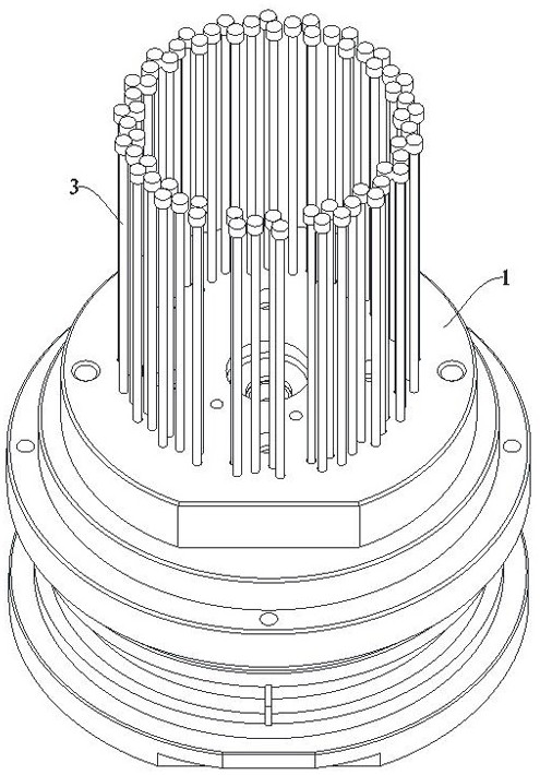
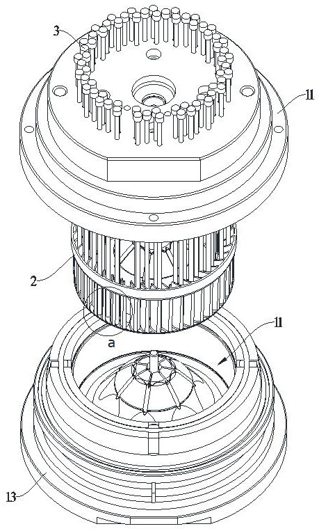
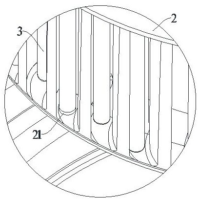
[0072] The first step is to set up 63 adjustment components 3, and label them in order, and make trial samples. Set the centrifugal balancing machine to the weighting method for calculation, and it is calculated that the samples need to be formed at the adjustment components 3 labeled a, b, and c. The mass of the balance part 21 is M a =3g, M b =1g and M c = 1g, the quality of the balance parts 21 that need to be formed at the remaining 60 adjustment components 3 is 0, and the quality data and the adjustment components 3 are recorded in one-to-one correspondence.

[0073] In the second step, the length H=M / (ρπR 2 ), where ρ is the density of the sample, ρ=1.13g / cm³, R is the radius of the balance part 21, R=0.5cm, bring in the above data and take two decimal places to get H a =3.38cm, H b =1.12cm, H c =1.12cm,.

[0074] In the third step, M a Correspondingly use the adjus...

Embodiment 2

[0078] A method for adjusting a dynamic balance processing mold, comprising the following steps:

[0079] The first step is to set 63 adjustment components 3, and label them in order, and make trial samples. Set the centrifugal balancing machine to the de-weighting method for calculation, and calculate the samples that need to be formed at the adjustment components 3 labeled d and e. The mass of the balance part 21 is respectively M d =-1g and M e =-1g, the quality of the balance parts 21 that need to be formed at the remaining 61 adjustment components 3 is 0, and the quality data and the adjustment components 3 are recorded in one-to-one correspondence.

[0080] In the second step, calculate the length H=M / (ρπR of the balance portion 21 at d and e places by mass data 2 ), where ρ is the density of the sample, ρ=1.13g / cm³, R is the radius of the balance part 21, R=0.5cm, bring in the above data and take two decimal places to get H d =-1.12cm, H e =-1.12cm.

[0081] In the...


PUM


Abstract

The invention discloses a dynamic balance machining die, an adjusting method and an operating method. The dynamic balance machining die comprises a die body, a cavity used for forming a rotary body is formed in the die body, a plurality of adjusting assemblies are arranged on the die body in the circumferential direction of the cavity, the adjusting assemblies are connected with the cavity, and the adjusting assemblies are suitable for being matched with the cavity to integrally form a balance part on the rotary body; and the adjusting assemblies are suitable for changing the size of the formed balance part through length adjustment, the balance part is suitable for enabling the rotary body to achieve rotating balance, the adjusting assemblies can assist the cavity in integrally forming the balance part on the rotary body, and the mass of the balance part can be changed along with movement of the adjusting assemblies. The dynamic balance treatment can be completed in the manufacturing process of the rotary body, the machining steps are reduced, the production efficiency is improved, the structural strength of the rotary body is improved, and the follow-up treatment difficulty is reduced.

Description

technical field [0001] The application relates to the technical field of injection molds, in particular to a dynamic balance processing mold, an adjustment method and an operation method. Background technique [0002] Because the position of each blade of the car air-conditioning fan is not uniform in order to obtain stronger wind power, the car air-conditioning fan needs to undergo a dynamic balance test before assembly to avoid vibration, abnormal noise or even affect normal use when the fan is running at high speed. The conventional dynamic balancing method is to install a balance weight or use a balance column, which can help the fan blade to balance the quality and make the fan run smoothly. [0003] However, the existing dynamic balancing process of the rotary body has the following defects: the balance weight may fall off during long-term use, causing the fan to be out of balance during the rotation process, and the balance column needs manual correction to adjust the...

Claims


Application Information

Patent Timeline
IPC IPC(8): B29C45/26B29C45/40
CPCB29C45/26B29C45/4005
Inventor 闫其洋
Owner NINGBO HENGFU AUTO PARTS DEV
Why Eureka
Try Eureka