Ventilating cage

A cage and air duct technology, applied in fruit hanging devices, botany equipment and methods, gardening, etc., can solve the problems of affecting the wind effect, deformation of the cage body, weakening of the strength of the orifice plate structure, etc., and achieve a large air volume , High structural strength, uniform air outlet effect

Pending Publication Date: 2018-12-28
林钢
View PDF2 Cites 0 Cited by
  • Summary
  • Abstract
  • Description
  • Claims
  • Application Information

AI Technical Summary

Problems solved by technology

[0003] The cross-section of the ventilation cage is usually U-shaped, and its overall shape is long and covered on the ground. When in use, grain piles will be directly piled up on the top and sides of the ventilation cage. It has high structural strength and avoids collapse under pressure. For this reason, corresponding reinforcement structures will be provided on the ventilation cage. For example, the Chinese invention patent application (201810220628.0) discloses an above-ground ventilation cage, including orifice plates, located on both sides of the orifice plate. The upper surface of the base is provided with positioning grooves, the orifice plate is inverted U-shaped and inserted into the positioning grooves of the base on both sides, fixed by fastening screws, the outer surface and inner surface of the orifice plate are respectively set There are dislocated and separated grooves, the grooves are inverted trapezoidal structures, and ventilation holes are arranged on the upper bottom and two waists of the trapezoidal structures. The ventilation cage directly processes the orifice plates used to open the ventilation holes into a trapezoidal arrangement structure to improve the pressure bearing capacity of the orifice plate, but due to the integrated structure of the orifice plate, the ventilation holes are directly opened on the orifice plate, and the orifice plate is used for both support and opening, resulting in the structure strength is weakened
Another example is the Chinese utility model patent application (application number: 01233950.4) which discloses a ventilation cage on the ground. Both ends of each cage are equipped with large and small ribs respectively. Although this structure has changed the reinforcement structure, two sections of reinforcement ribs are used, and the inside is equipped with pull rods for pulling, but the ventilation holes are also directly opened on the cage body for support. , the weakened cage body is prone to local deformation under pressure, which affects the wind effect

Method used


Image

  • Ventilating cage
  • Ventilating cage
  • Ventilating cage

Examples


Embodiment Construction

[0036] The following are specific embodiments of the present invention and in conjunction with the accompanying drawings, the technical solutions of the present invention are further described, but the present invention is not limited to these embodiments.

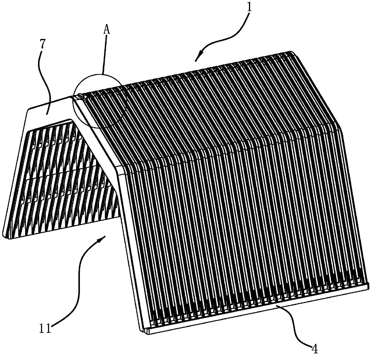
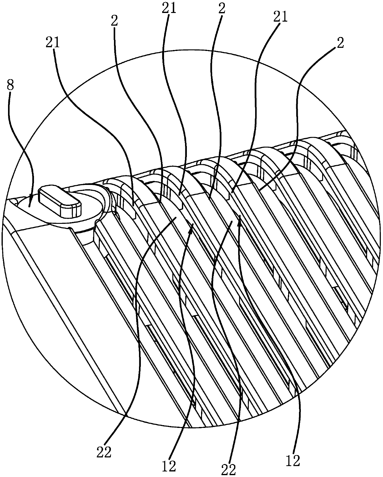
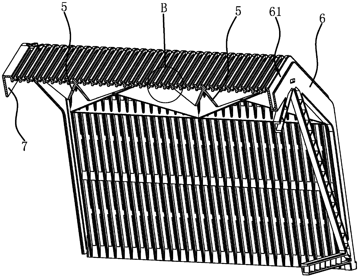
[0037] like figure 1 , figure 2 As shown, a ventilated cage includes a cage body 1, the cage body 1 is made of nylon plastic, the cage body 1 includes a number of elongated skeletons 2, and the several skeletons 2 are all arched upwards, and the several skeletons 2 are arranged at intervals in turn and They are fixedly connected to each other, and the inner sides of several skeletons 2 form air ducts 11 through which both ends are connected. The skeletons 2 are plate-shaped, and combined image 3 , Figure 4 As shown, one side of the skeleton 2 has an outer rib 21 arranged along the length direction, and the other side of the skeleton 2 has an inner rib 22 arranged along the length direction, and the outer rib 21 of the...


PUM


Abstract

The invention provides a ventilating cage, belongs to the technical field of ventilating equipment, and solves the problem that the existing ventilating cage is weak in structural strength. The ventilating cage comprises a cage body with an air channel; the cage body comprises a plurality of strip-shaped upward arched skeletons; the plurality of the skeletons are arranged at intervals in sequenceand are connected with one another; the air channel is formed inside the plurality of the skeletons; external reinforcing ribs which are arranged in the length direction are arranged on one side of the skeletons; internal reinforcing ribs which are arranged in the length direction are arranged on the other side of the skeletons; and an air outlet which communicates with the air channel is formed between each external reinforcing rib of the corresponding skeleton and the internal reinforcing rib of the adjacent skeleton on one side. The ventilating cage has a good ventilating effect on the basis of ensuring high structural strength.

Description

technical field [0001] The invention belongs to the technical field of ventilation equipment and relates to a ventilation cage. Background technique [0002] The ventilation cage is a kind of ventilation duct installed on the ground, which is connected with the fan and other wind sources. The ventilation holes are evenly opened on the ventilation cage. The airflow generated by the fan flows along the ventilation cage and is discharged from the ventilation holes. The main Used in room-type granaries and open-air bulk grain stacks, it can make the air flow evenly enter the grain stacks, effectively implement multi-directional operations such as cooling, precipitation, chemical fumigation, air conditioning, conditioning, removal of residual poisons, and odors, etc., suitable for wheat , rice, corn, soybeans and other long-term storage, it is the most ideal ventilation equipment for central storage, national storage, and local large-scale grain depots. [0003] The cross-sectio...

Claims


Application Information

Patent Timeline
Patent Type & Authority Applications(China)
IPC IPC(8): A01F25/22A01F25/16
CPCA01F25/22A01F25/16
Inventor 林钢
Owner 林钢
Why Eureka
Try Eureka