Super-resolution microscopic CT imaging system

A CT imaging and super-resolution technology, used in microscopes, optics, instruments, etc., can solve problems such as the upper limit of resolution

Active Publication Date: 2018-02-09
CAPITAL NORMAL UNIVERSITY +1
View PDF5 Cites 8 Cited by
  • Summary
  • Abstract
  • Description
  • Claims
  • Application Information

AI Technical Summary

Problems solved by technology

Considering the actual application requirements and hardware limitations, such as the field of view, the pixel size of scientific-grade camera chips, etc., the resolution of existing systems of this type has an upper limit for a given imaging field of view

Method used


Image

  • Super-resolution microscopic CT imaging system
  • Super-resolution microscopic CT imaging system
  • Super-resolution microscopic CT imaging system

Examples


Embodiment Construction

[0024] In the drawings, the same or similar reference numerals are used to denote the same or similar elements or elements having the same or similar functions. Embodiments of the present invention will be described in detail below in conjunction with the accompanying drawings.

[0025] In the description of the present invention, the terms "central", "longitudinal", "transverse", "front", "rear", "left", "right", "vertical", "horizontal", "top", " The orientation or positional relationship indicated by "bottom", "inner", "outer", etc. is based on the orientation or positional relationship shown in the drawings, and is only for the convenience of describing the present invention and simplifying the description, rather than indicating or implying the referred device or element Must have a specific orientation, be constructed and operate in a specific orientation, and therefore should not be construed as limiting the scope of the invention.

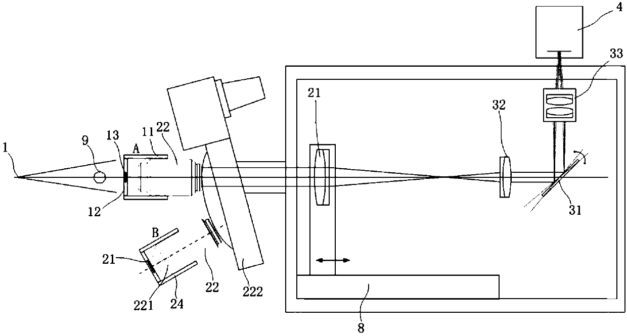
[0026] Such as figure 1 As shown, ...


PUM


Abstract

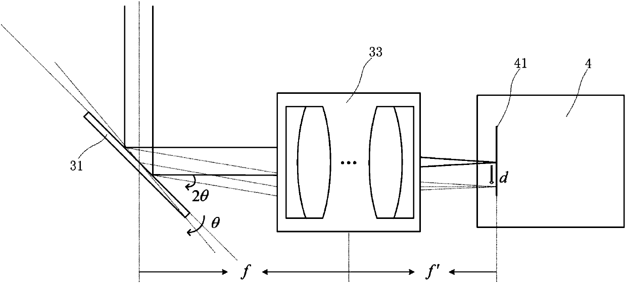
The invention discloses a super-resolution microscopic CT imaging system. The system includes an X-ray source, an X-ray conversion visible light device, a microscopic imaging device, a relay imaging device, a scientific grade camera, a multi-axis loading motion device, and a control device. An X-ray emitted by the X-ray source penetrates a measured object, and is converted into a 2D visible lightfield distribution by the X-ray conversion visible light device. The 2D visible light field distribution is propagated backward from the exit surface of the X-ray conversion visible light device and is projected as the object side onto the microscopic imaging device, and first microscopic amplification imaging is carried out on the 2D visible light field distribution via the microscopic imaging device. Then, the 2D visible light field distribution is projected onto the relay imaging device, and second relay amplification imaging is carried out on the 2D visible light field distribution via therelay imaging device. The relay imaging device includes a sub-pixel scanning member disposed on a parallel light path of the relay imaging device. The sub-pixel scanning member is used for making anoverall 2D image on the imaging plane of the relay imaging device carry out sub-pixel 2D translation in a vertical axis plane, so as to get a series of 2D images with pixels subdivided. The limitationcaused by the original imaging hardware of the system is broken, and super-resolution imaging is realized.

Description

technical field [0001] The present invention relates to the technical field of micro-CT (full name in English is "computed tomography"), in particular to a super-resolution micro-CT imaging system. Background technique [0002] The micro-CT system based on optocouplers and visible light scientific cameras is currently the world's leading high-resolution X-ray imaging technology. Scientific grade camera on a chip. Compared with conventional X-ray imaging based on a flat-panel scientific camera, this type of imaging method can not only perform geometric projection magnification in the X-ray part, but also use an optical microscope system for secondary magnification to achieve higher resolution X-ray imaging. In this type of system, the final imaging resolution is determined by the magnification of the microscope objective lens, the numerical aperture (NA) and the pixel size of the camera chip. Considering the actual application requirements and hardware limitations, such as...

Claims


Application Information

Patent Timeline
Patent Type & Authority Applications(China)
IPC IPC(8): G02B21/36
CPCG02B21/367
Inventor 朱溢佞毛珩翟慕岳张慧滔未永傅鹏
Owner CAPITAL NORMAL UNIVERSITY
Why Eureka
Try Eureka