Power monitoring device and method
A technology of power monitoring and power value, which is applied in the field of communication, can solve the problems of inability to monitor antenna power conveniently and remotely, and achieve the effect of solving large power reading errors and improving accuracy
- Summary
- Abstract
- Description
- Claims
- Application Information
AI Technical Summary
Problems solved by technology
Method used
Image

Examples
Embodiment 1
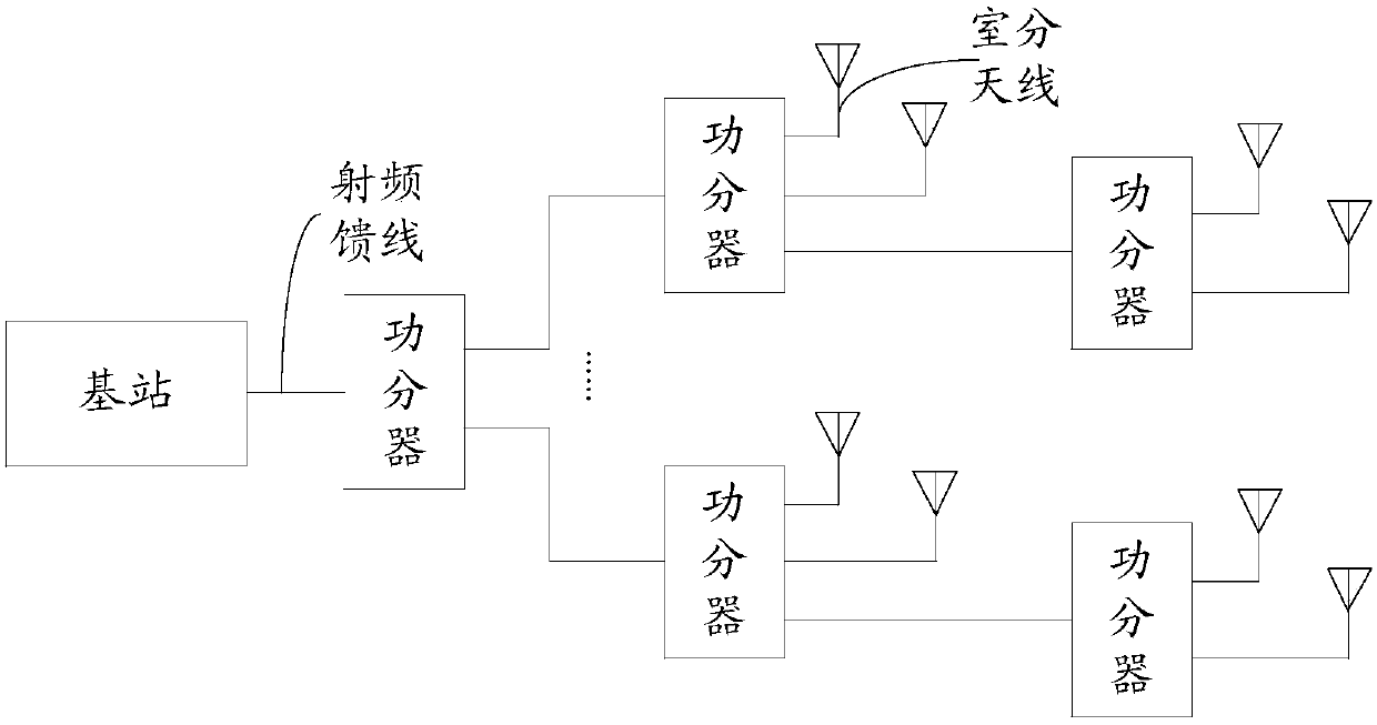
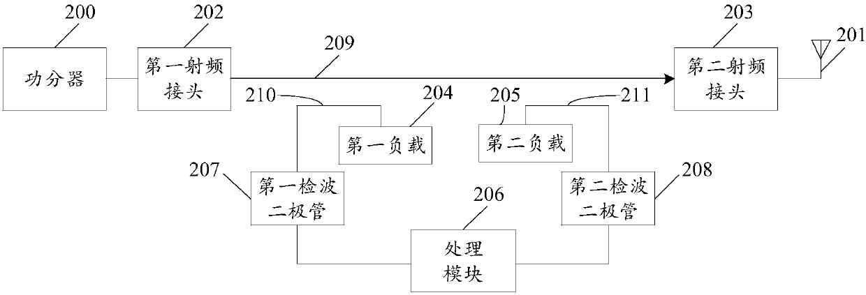
[0051] Such as figure 2 As shown, the embodiment of the present invention provides a device for power monitoring. When the antenna is connected to the base station through a power splitter, the device is installed between the power splitter 200 and the antenna 201. The device includes: a first RF joint 202, second radio frequency joint 203, first load 204, second load 205, processing module 206, first detection diode 207 and second detection diode 208, wherein:
[0052]One end of the first radio frequency joint 202 is connected to the power splitter 200, the other end is connected to one end of the second radio frequency joint 203 through a first microstrip line 209, and the other end of the second radio frequency joint 203 is connected to the power divider 200. The antenna 201 is connected;
[0053] The anode of the first detection diode 207 is connected to the first load 204 through the second microstrip line 210, the cathode of the first detection diode 207 is connected t...
Embodiment 2
[0089] Such as Figure 7 As shown, Embodiment 2 of the present invention provides a method of power monitoring based on the device described in Embodiment 1 of the present invention, the method comprising:
[0090] S701. Correspondingly converting the first radio frequency signal and the second radio frequency signal into a first digital signal and a second digital signal;
[0091] Wherein, the first radio frequency signal and the second radio frequency signal are signals output by the first detection diode and the second detection diode in the device according to Embodiment 1 of the present invention, respectively.
[0092] S702. Determine a first power value and a second power value respectively corresponding to the first digital signal and the second digital signal;
[0093] Wherein, the method for determining the power value corresponding to the digital signal is the same as the method in the prior art, and will not be repeated in the present invention.
[0094] S703. Ob...
PUM
 Abstract
Description
Claims
Application Information
 - R&D
- Intellectual Property
- Life Sciences
- Materials
- Tech Scout
- Unparalleled Data Quality
- Higher Quality Content
- 60% Fewer Hallucinations
Browse by: Latest US Patents, China's latest patents, Technical Efficacy Thesaurus, Application Domain, Technology Topic, Popular Technical Reports.
© 2025 PatSnap. All rights reserved.Legal|Privacy policy|Modern Slavery Act Transparency Statement|Sitemap|About US| Contact US: help@patsnap.com