Implementation method of reinforcement cage forming device for pile hole foundation

A steel skeleton and forming device technology, applied in the field of building construction, can solve the problems that the strength of pile holes cannot meet the requirements of building construction, the effect of transverse reinforcement welding is not ideal, and the distribution of transverse reinforcement is uneven, so as to avoid swing and radial swing. Eliminate and improve the effect of distribution uniformity

Active Publication Date: 2018-02-13
东莞市建安管桩有限公司
View PDF10 Cites 2 Cited by
  • Summary
  • Abstract
  • Description
  • Claims
  • Application Information

AI Technical Summary

Problems solved by technology

[0003] According to the depth of the pile hole, the axial length of the general steel cage is the same as the depth of the pile hole. However, when pouring a pile hole with a relatively long depth, the construction personnel usually splice multiple steel cages of equal length, and then hoist them to In the pile hole, concrete is poured at the end to shorten the construction time; however, since there are many longitudinal bars on the steel cage and they are distributed in a circle, that is, each longitudinal bar needs to be fixed one by one durin

Method used


Image

  • Implementation method of reinforcement cage forming device for pile hole foundation
  • Implementation method of reinforcement cage forming device for pile hole foundation
  • Implementation method of reinforcement cage forming device for pile hole foundation

Examples


Embodiment 1

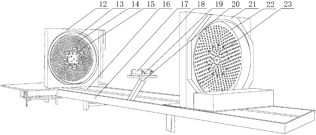
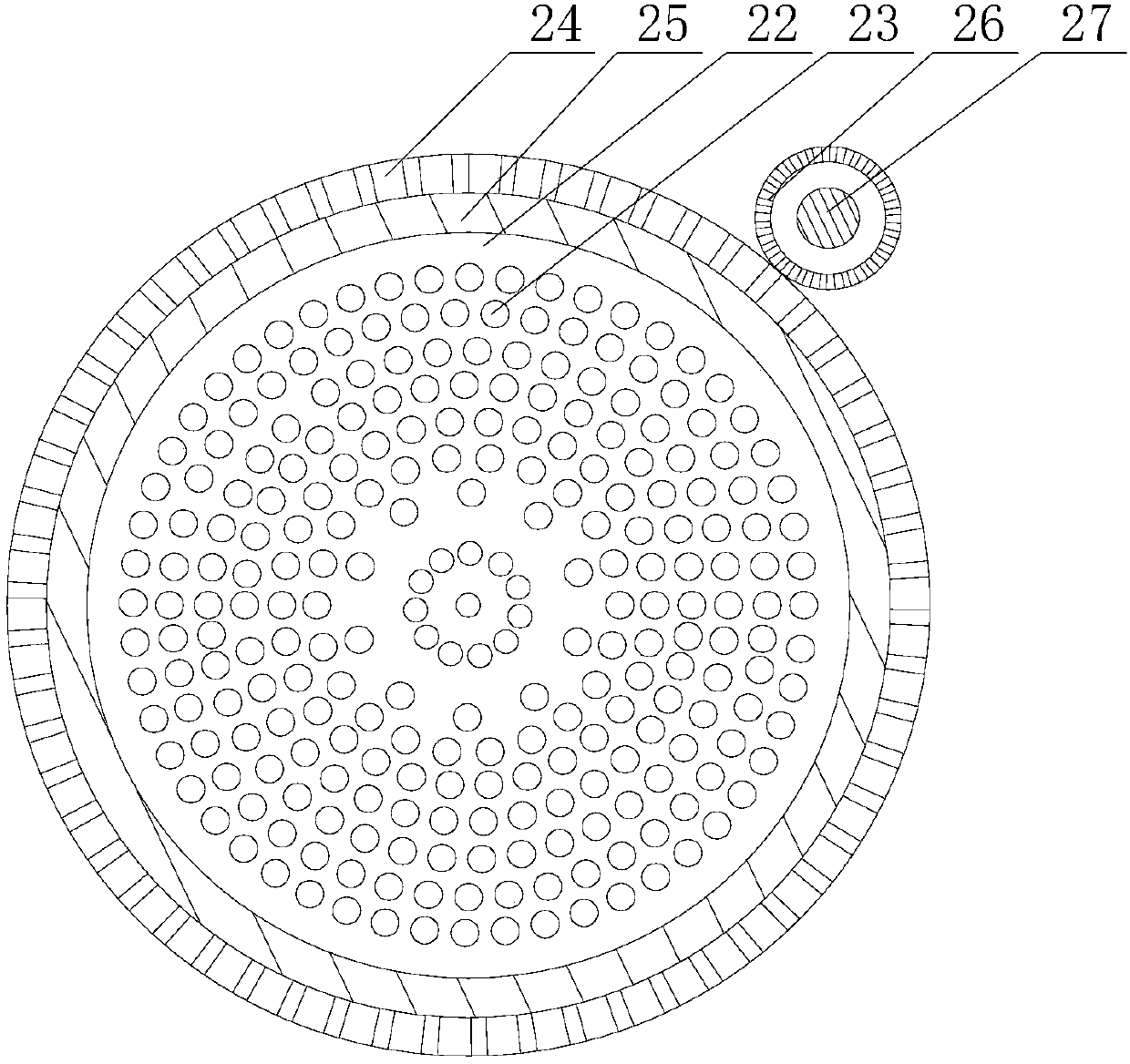
[0029] Such as Figure 1~5 As shown, this embodiment includes the following steps: including the following steps: first, fix a plurality of fixing components on the first turntable and the second turntable respectively, so as to form two concentric and equal-diameter circles; Adjust the distance between the first support plate and the second support plate according to the length, and then insert the multiple longitudinal ribs required by the reinforcement cage into the butt holes and the fixing components on the mounting holes in sequence, and start the machine fixed on the second turntable. The motor, the motor drives the gear to mesh with the toothed belt, so that the second turntable starts to rotate inside the two bearings, the first turntable is linked through the longitudinal ribs, and the first turntable also rotates synchronously while the second turntable rotates; the transverse ribs According to the spiral trajectory, it is distributed on the skeleton structure forme...

Embodiment 2

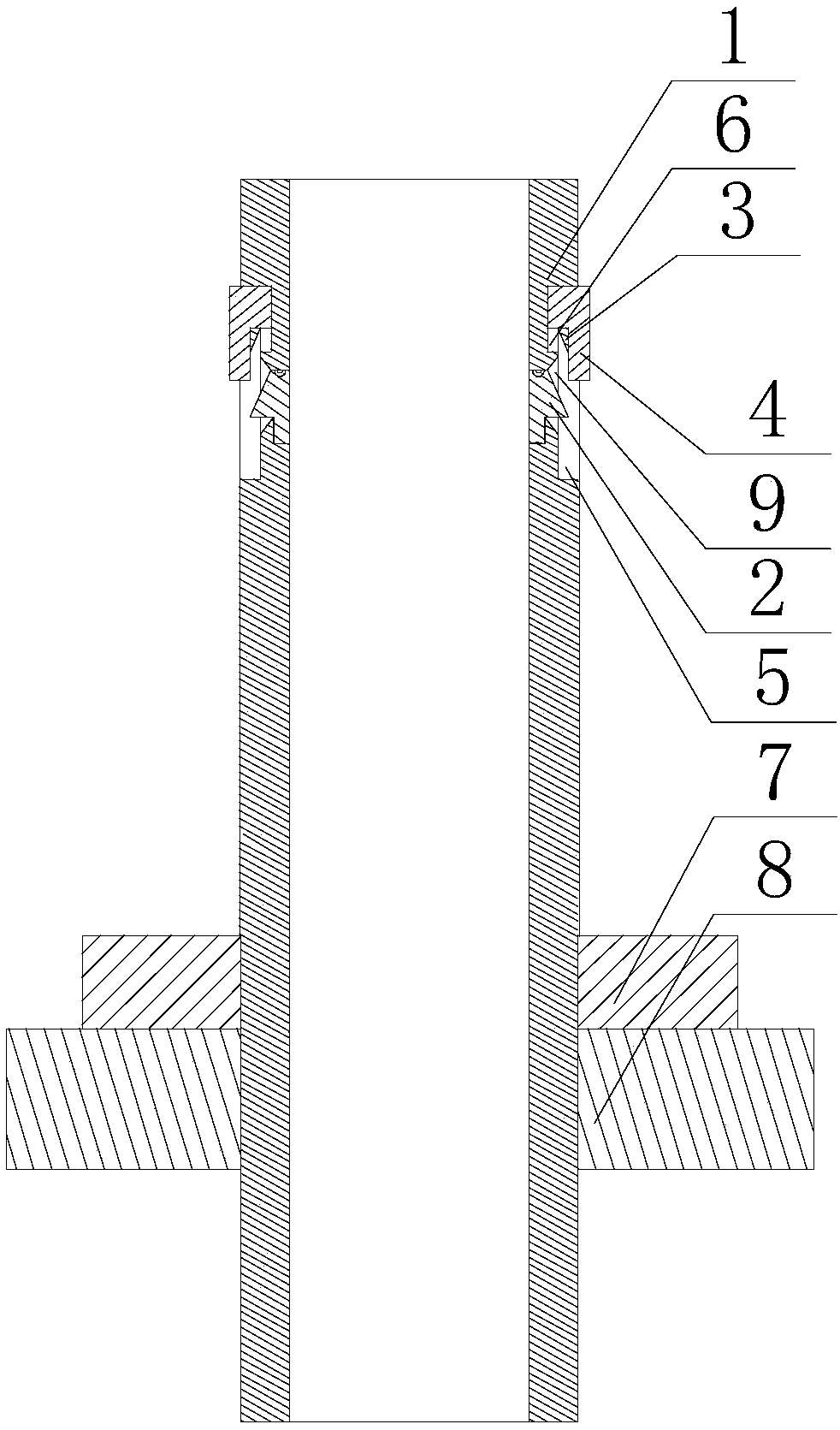
[0034] Such as Figure 1~5 As shown, in this embodiment, transition arcs 11 are respectively provided on both sides of the contact block 10. When the pressure block 2 rotates along the circumferential direction of the annular groove 9 to contact with the contact block 10, the inner side wall of the pressure block 2 and the A smooth transition is realized between the outer side walls of the contact block 10 . When the pressure ring 4 is adjusted to be in contact with the outer side wall of the contact block 10, since the inner peripheral wall of the protrusion 3 is smooth, the two ends of the contact block 10 on the circumferential track of the limit groove 5 are likely to collide with the inner peripheral wall of the protrusion 3. Scratching causes the protrusion 3 to be damaged, so that the adjustment accuracy of the protrusion 3 in the later period is reduced. For this, the applicant sets excessive arcs at the two ends of the protrusion 3, so that the inner wall of the protr...


PUM


Abstract

The invention discloses an implementation method of a reinforcement cage forming device for a pile hole foundation. The method includes: fixing a plurality of fixing components on a first rotary discand a second rotary disc to form two concentric and unidiameter circles; regulating the interval between a first support plate and a second support plate according to the axial length of a reinforcement cage, inserting a plurality of longitudinal reinforcing steel bars needed by the reinforcement cage into the fixing components on butt joint holes and mounting holes; starting a motor to allow themotor to drive a gear to mesh with a toothed belt, and allowing the second rotary disc to rotate inside two bearings, and allowing the first rotary disc to rotate synchronously; arranging transverse reinforcing steel bars on the reinforcement cage structure formed by the longitudinal reinforcing steel bars, and welding the connecting points of the transverse reinforcing steel bars and the longitudinal reinforcing steel bars until the transverse reinforcing steel bars completely wind the reinforcement cage structure. The method has the advantages that during the winding, the longitudinal reinforcing steel bars are constantly clamped and fixed by the fixing components, and the welding effect between the longitudinal reinforcing steel bars and the transverse reinforcing steel bars is prevented from being affected by the fact that the longitudinal reinforcing steel bars turn in barrels.

Description

technical field [0001] The invention relates to the field of building construction, in particular to an implementation method of a steel bar skeleton forming device for a pile hole foundation. Background technique [0002] During the construction of bridges, culverts or high-rise buildings, the foundation may be piled according to requirements. The method is to use machine punching and water mill drilling, and the hole depth meets the design requirements, and then lower the reinforcement cage to the pile hole, and then insert the conduit for concrete pouring . And when the concrete structure is a columnar or strip-shaped member, the central part does not need to be reinforced, and only the reinforcement is arranged under the surface of the concrete member that contacts the air. If the component is independent, it is necessary to prefabricate the reinforcement around the component during construction, and usually the prefabricated reinforcement structures such as bored piles...

Claims


Application Information

Patent Timeline
IPC IPC(8): B21F31/00
CPCB21F31/00
Inventor 杨蒙蒙
Owner 东莞市建安管桩有限公司
Why Eureka
Try Eureka