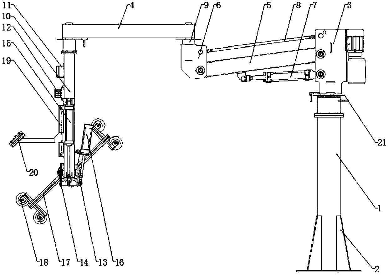
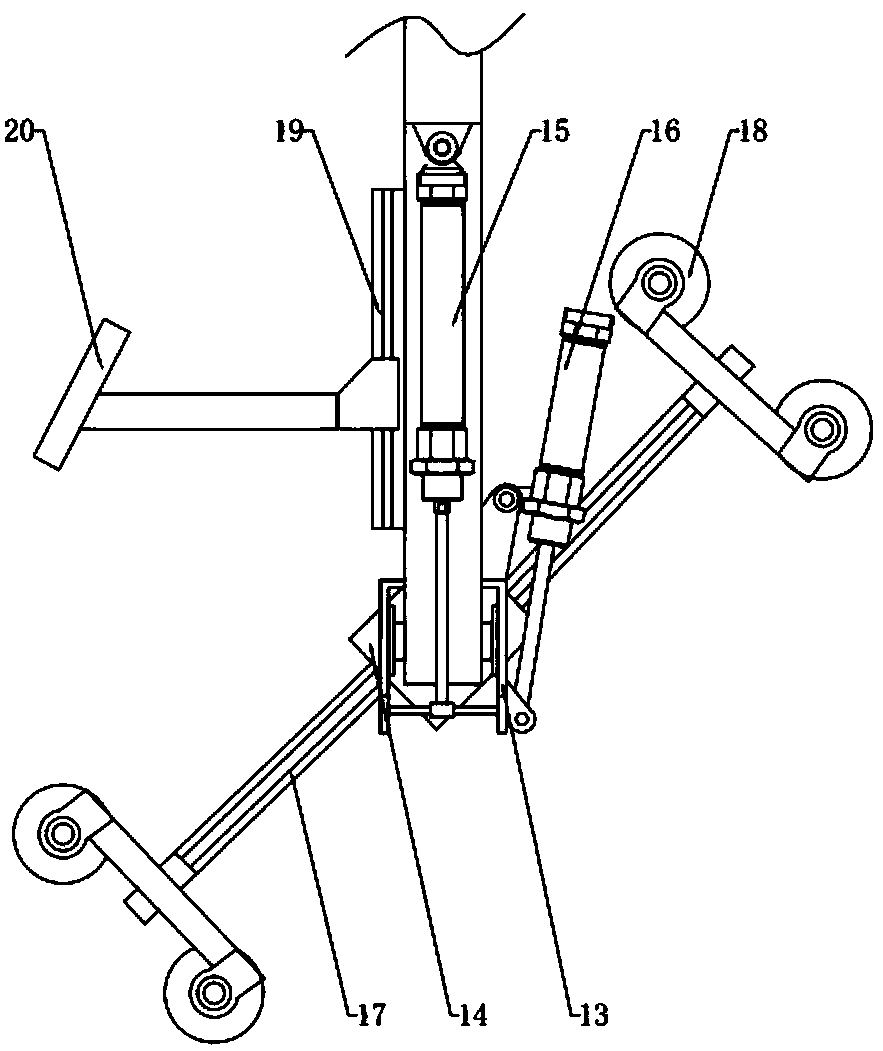
Workpiece carrying device

A technology for handling devices and workpieces, which is applied in the direction of transportation, packaging, and conveyor objects. It can solve problems such as low labor efficiency, heavy workpiece weight, and difficulty in ensuring accuracy, and achieves convenient removal of workpieces, easy handling, and high safety performance. Effect

Inactive Publication Date: 2018-02-13
天津市津廊宏业工程机械液压设备有限公司
View PDF6 Cites 9 Cited by
  • Summary
  • Abstract
  • Description
  • Claims
  • Application Information

AI Technical Summary

Problems solved by technology

[0002] In the process of mechanical processing and manufacturing, it is often necessary to transport the workpiece from one place to another. Sometimes due to the heavy weight of the workpiece, or the accuracy requirements of the handling position, or the harsh environment of the handling, at present, in the processing of mechanical workpieces, the general workers are loading When clamping workpieces, the weight of manual loading and unloading can only be about 30-40 kilograms. In a workshop or research room without crane equipment, it is very difficult to hoist equipment, clamp workpieces, and carry heavy objects weighing hundreds of kilograms.
There is also the loading and unloading of goods by general trucks. It is also very difficult to manually load and unload goods weighing 100-200 kg.
It is also difficult to manually carry 100-200 kg of goods, the labor efficiency is low, and the accuracy is difficult to guarantee
Sometimes the workpiece cannot be transported in a straight line relative to the processing equipment

Method used


Image

  • Workpiece carrying device
  • Workpiece carrying device

Examples


Embodiment Construction

[0023] First of all, it should be noted that the specific structure, features and advantages of the present invention will be specifically described below by way of examples, but all descriptions are only for illustration, and should not be construed as forming any limitation on the present invention . In addition, any single technical feature described or implied in each embodiment mentioned herein, or any single technical feature shown or implied in each drawing, can still be described in these technical features (or their equivalents) ) to continue any combination or deletion, so as to obtain more other embodiments of the present invention that may not be directly mentioned herein. In addition, for the sake of simplifying the drawings, the same or similar technical features may only be marked in one place in the same drawing.

[0024] It will be understood that when a component is referred to as being "connected" to another component, it can be directly connected to the ot...


PUM


Abstract

The invention relates to a workpiece carrying device. The workpiece carrying device comprises a main vertical column, a cantilever and a front vertical shaft. A base is arranged at the lower end of the main vertical column; a main mounting frame is rotatably connected with the main vertical column through a first-stage rotary bearing; the cantilever comprises a front cantilever body and a rear cantilever body; the top of the front vertical shaft is rotatably connected with the other end of the front cantilever body through a third-stage rotary bearing; an electrical control box, a pneumatic valve set, a suction disc set pneumatic turnover device, a suction disc set pneumatic angle adjusting device and a turnover base are sequentially arranged on the front vertical shaft from top to bottom;the turnover base is movably connected with the bottom of the front vertical shaft through a connecting shaft; a suction disc bracket seat is rotatably arranged at the end, away from the front vertical shaft, of the turnover base; the suction disc set pneumatic angle adjusting device comprises a secondary air cylinder hinged to the turnover base; the free end of a telescopic rod of the secondaryair cylinder is hinged to the suction disc bracket seat; suction disc brackets are arranged at the end, away from the turnover base, of the suction disc bracket seat; and suction discs are arranged onthe suction disc brackets. The hydraulic power assisting and pneumatic transmission principle is adopted, and upper and lower operation, left and right operation, and front and rear operation of thesuction discs can be achieved.

Description

technical field [0001] The invention belongs to the technical field of workpiece handling, and in particular relates to a workpiece handling device. Background technique [0002] In the process of mechanical processing and manufacturing, it is often necessary to transport the workpiece from one place to another. Sometimes due to the heavy weight of the workpiece, or the accuracy requirements of the handling position, or the harsh environment of the handling, at present, in the processing of mechanical workpieces, the general workers are loading When clamping workpieces, the weight of manual loading and unloading can only be about 30-40 kilograms. In a workshop or research room without crane equipment, it is very difficult to hoist equipment, clamp workpieces, and carry heavy objects weighing hundreds of kilograms. . There is also the loading and unloading of goods by general trucks, and manual loading and unloading of goods weighing 100-200 kg is also very difficult. It is...

Claims


Application Information

Patent Timeline
Patent Type & Authority Applications(China)
IPC IPC(8): B65G47/91
CPCB65G47/914
Inventor 王凤荣
Owner 天津市津廊宏业工程机械液压设备有限公司
Why Eureka
Try Eureka