Anti-swinging device for lifting appliance for bridge type crane

A bridge crane and anti-swing device technology, which is applied in the direction of walking bridge cranes, cranes, transportation and packaging, etc., can solve the problem of material loading and unloading speed that affects production efficiency, difficulty in positioning the final position of the spreader, and limited lifting height and other issues to achieve the effect of reducing the possibility of dangerous accidents, avoiding swings, and accurate distance

Inactive Publication Date: 2018-02-13
ANHU WUHU CHANGJIANG JACK UP EQUIP CO LTD
View PDF8 Cites 4 Cited by
  • Summary
  • Abstract
  • Description
  • Claims
  • Application Information

AI Technical Summary

Problems solved by technology

[0003] During the material lifting process of the bridge crane, due to the high-speed operation of the crane trolley, more and more time is spent on eliminating the swing of the spreader and quickly and accurately positioning it, which greatly affects the production efficiency and the loading and unloading speed of materials, and It brings hidden dangers to safe production, so the anti-swing design of the spreader is particularly important. At present, the anti-swing methods of the spreader mainly include mechanical anti-swing and electronic anti-swing. With the widespread use of these two anti-swing devices, The shortcomings of mechanical anti-swing and electronic anti-swing are also increasingly exposed. Among them, the lifting height of the mechanical anti-swing device is limited. The anti-swing effect is improved; and the electronic anti-swing method makes it very difficult to locate the final position of the spreader, and it is easy to cause operator fatigue

Method used


Image

  • Anti-swinging device for lifting appliance for bridge type crane
  • Anti-swinging device for lifting appliance for bridge type crane
  • Anti-swinging device for lifting appliance for bridge type crane

Examples


Embodiment

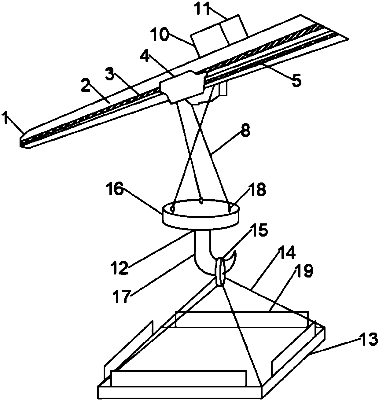
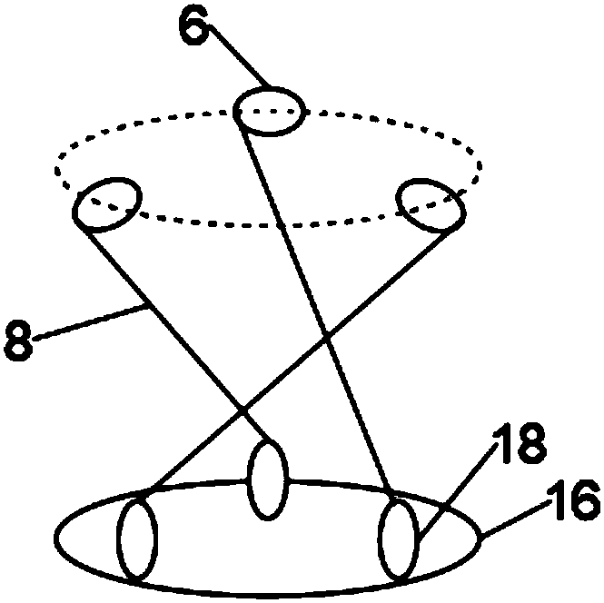
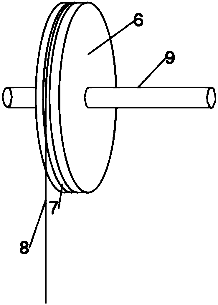
[0026] Such as Figure 1 to Figure 4 As shown, a suspension anti-swing device for a bridge crane includes a bridge 1, and the bridge 1 includes a main girder 2 of a box-type structure, and rails 3 are welded on both front and rear sides of the main girder 2, A slider 4 is arranged below the main beam 2, and a hydraulic rod 5 is arranged at the right end of the slider 4. The hydraulic rod 5 realizes expansion and contraction under the control of the control system, thereby completing the lateral movement of the slider 4 on the track 3. movement, the inside of the slider 4 is a hollow structure, and the top and bottom ends of the slider 4 are open, the slider 4 is clamped on the track 3, and the slider 4 can move along the track 3 Lateral movement, three reels 6 are installed on the inner wall of the slider 4, grooves 7 are all arranged on the three reels 6, steel wire ropes 8 are arranged inside the grooves 7, and a steel wire rope 8 is arranged inside the three reels 6. The w...


PUM


Abstract

The invention discloses an anti-swinging device for a lifting appliance for a bridge type crane. The anti-swinging device comprises a bridge which comprises a main beam, tracks are welded to the frontside face and the rear side face of the main beam correspondingly, and a sliding block is arranged below the main beam. A hydraulic rod is arranged at the right end of the sliding block, the slidingblock is clamped to the tracks, and three rolls are mounted on the inner wall of the sliding block. Grooves are formed in the three rolls correspondingly, steel wire ropes are arranged in the groovescorrespondingly, and rotary shafts are arranged in the centers of the three rolls correspondingly. One ends of the rotary shafts are connected with a motor through a belt, the motor is connected witha frequency changer, and the lower ends of the steel wire ropes are connected with a hanger. A consigning plate is arranged below the hanger, branched ropes are arranged at the four corners of the consigning plate, and one ends of the branched ropes are jointly connected with a hanging ring. The hanging ring is hung on the hanger, the function of material hanging can be achieved, shaking can be reduced in the use process, the stability of the lifting appliance for the bridge type crane is improved, the problems put forward by the background technology can be effectively solved, and the anti-swinging device is worth popularizing.

Description

technical field [0001] The invention relates to the technical field of cranes, in particular to an anti-swing device for a spreader of a bridge crane. Background technique [0002] The bridge crane is a lifting device that is placed horizontally over the workshop, warehouse and stockyard for material lifting. Because its two ends are located on tall cement columns or metal supports, it is named after the shape of a bridge. The bridge crane The bridge frame runs longitudinally along the rails laid on the elevated sides on both sides, which can make full use of the space under the bridge frame to lift materials without being hindered by ground equipment. It is the most widely used and most numerous hoisting machinery. [0003] During the lifting and transportation of materials by bridge cranes, due to the high-speed operation of the crane trolley, more and more time is spent on eliminating the swing of the spreader and quickly and accurately positioning it, which greatly affec...

Claims


Application Information

Patent Timeline
Patent Type & Authority Applications(China)
IPC IPC(8): B66C13/06B66C1/16B66C17/00
CPCB66C13/06B66C1/16B66C17/00
Inventor 焦来文
Owner ANHU WUHU CHANGJIANG JACK UP EQUIP CO LTD
Why Eureka
Try Eureka