Eureka AIR delivers breakthrough ideas for toughest innovation challenges, trusted by R&D personnel around the world.

Multi-arm lifting synchronous shaft structure

A technology of synchronous shaft and lifting frame, applied in the direction of hoisting device, hoisting device, etc., can solve the problems of complex structure, large space occupation, poor stability and reliability, etc., and achieve the effect of simple structure and stable lifting process

Pending Publication Date: 2018-02-13
江苏港星方能超声洗净科技有限公司
View PDF0 Cites 0 Cited by
  • Summary
  • Abstract
  • Description
  • Claims
  • Application Information

AI Technical Summary

Problems solved by technology

[0002] When the material is being cleaned, the material is usually put into the cleaning tooling basket first, and then the tooling basket is transported through the hook device in the cleaning equipment. During this process, the hook device needs to be lifted and transported horizontally. Most existing equipment uses The motor is used with the lead screw, etc., and the structure is complex and takes up a lot of space, while the device with a simple structure has poor stability and reliability.

Method used


Image

  • Multi-arm lifting synchronous shaft structure
  • Multi-arm lifting synchronous shaft structure
  • Multi-arm lifting synchronous shaft structure

Examples


Embodiment Construction

[0017] The technical solutions in the embodiments of the present invention will be described in detail below in conjunction with the accompanying drawings in the embodiments of the present invention. Obviously, the described embodiments are only some of the embodiments of the present invention, not all of them. Based on the embodiments of the present invention, all other embodiments obtained by persons of ordinary skill in the art without making creative efforts belong to the protection scope of the present invention.

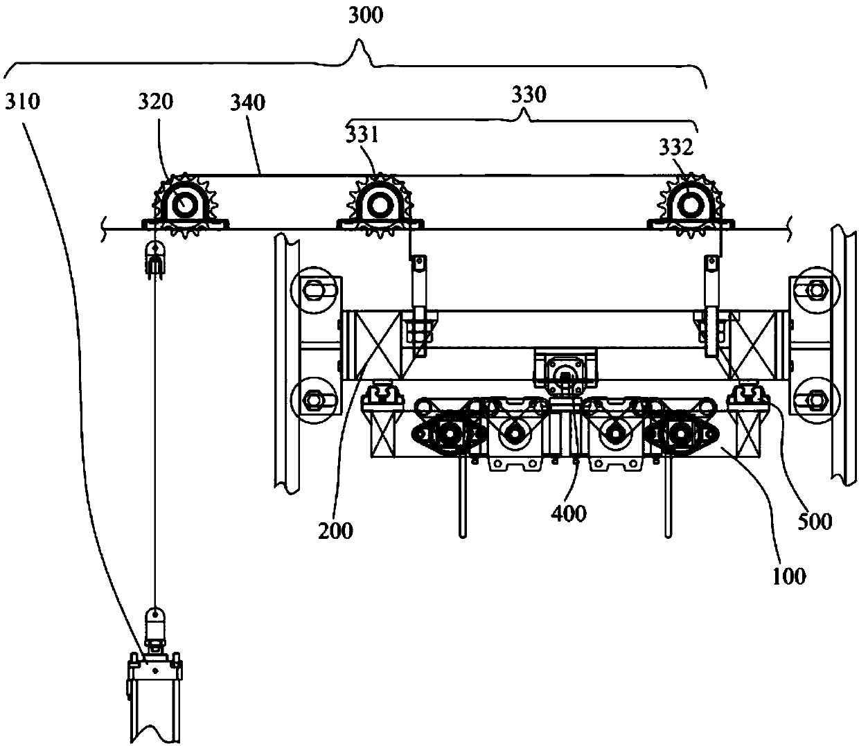
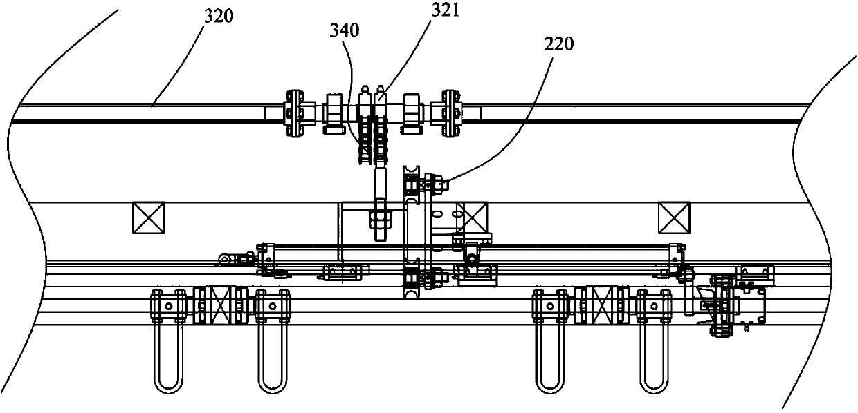
[0018] ginseng Figure 1 to Figure 5 As shown, the multi-arm lifting synchronous shaft structure in this embodiment includes a hook frame 100, a lifting frame 200, a lifting device 300 and a moving device 400, and the hook frame 100 is slidably fixed on the bottom of the lifting frame 200 through a guide rail 500. The mobile device 400 is a mobile oil cylinder, which is arranged parallel to the guide rail 500. The mobile device 400 is fixed below the lifting fr...


PUM


Abstract

The invention discloses a multi-arm lifting synchronous shaft structure. The multi-arm lifting synchronous shaft structure comprises a hook support, a lifting support, a lifting device and a moving device; the hook support is slidably fixed to the lower portion of the lifting support through a guiding rail, the moving device is a moving oil cylinder, the moving oil cylinder is arranged in parallelwith the guiding rail, the moving device is fixed to the lower portion of the lifting support, and a piston rod of the moving device is hinged to the hook support; the lifting device comprises multiple lifting oil cylinders, a driving shaft, a reversing chain wheel and a chain arranged corresponding to the reversing chain wheel, the multiple lifting oil cylinders are arranged on one side of the lifting support at equal intervals, duplex chain wheels corresponding to the lifting oil cylinders are arranged on the driving shaft, one end of the chain is connected to the lifting oil cylinders, andone side of the end, back from the lifting oil cylinders, of the chain is connected to the lifting support after passing by the corresponding duplex chain wheels and the reversing chain wheel. The multi-arm lifting synchronous shaft structure is stable and reliable.

Description

technical field [0001] The present application relates to the field of high-reliability precision machinery, in particular to a multi-arm lifting synchronous shaft structure. Background technique [0002] When the material is being cleaned, the material is usually put into the cleaning tooling basket first, and then the tooling basket is transported through the hook device in the cleaning equipment. During this process, the hook device needs to be lifted and transported horizontally. Most existing equipment uses The motor is used in conjunction with a lead screw, etc., and has a complex structure and takes up a lot of space, while a device with a simple structure has poor stability and reliability. Therefore need to propose improvement. Contents of the invention [0003] The purpose of the present invention is to provide a multi-arm lifting synchronous shaft structure to overcome the deficiencies in the prior art. [0004] To achieve the above object, the present inventi...

Claims


Application Information

Patent Timeline
IPC IPC(8): B66F19/00
CPCB66F19/00B66F2700/05B66F2700/052
Inventor 朱黎斌汤飞何烨华宋海兵
Owner 江苏港星方能超声洗净科技有限公司
Why Eureka
Eureka Blog
Learn More