Clamping device for steel bar pulling-out and steel bar pulling-out method

A clamping device and clamping technology, which is applied in construction, building maintenance, building construction, etc., can solve problems that affect the construction progress and quality of the project, and the construction is abandoned halfway, so as to achieve the effect of enhancing the stability of the operation

Pending Publication Date: 2018-02-13
上海开普天岩土科技集团有限公司 +1
View PDF5 Cites 0 Cited by
  • Summary
  • Abstract
  • Description
  • Claims
  • Application Information

AI Technical Summary

Problems solved by technology

The existence of underground obstacles often leads to rerouting, relocation or redesign, resulting in halfway construction, which directly affects the construction progress and quality of the project. Therefore, it is very important to remove underground obstacles such as steel bars.

Method used


Image

  • Clamping device for steel bar pulling-out and steel bar pulling-out method
  • Clamping device for steel bar pulling-out and steel bar pulling-out method
  • Clamping device for steel bar pulling-out and steel bar pulling-out method

Examples


Embodiment 1

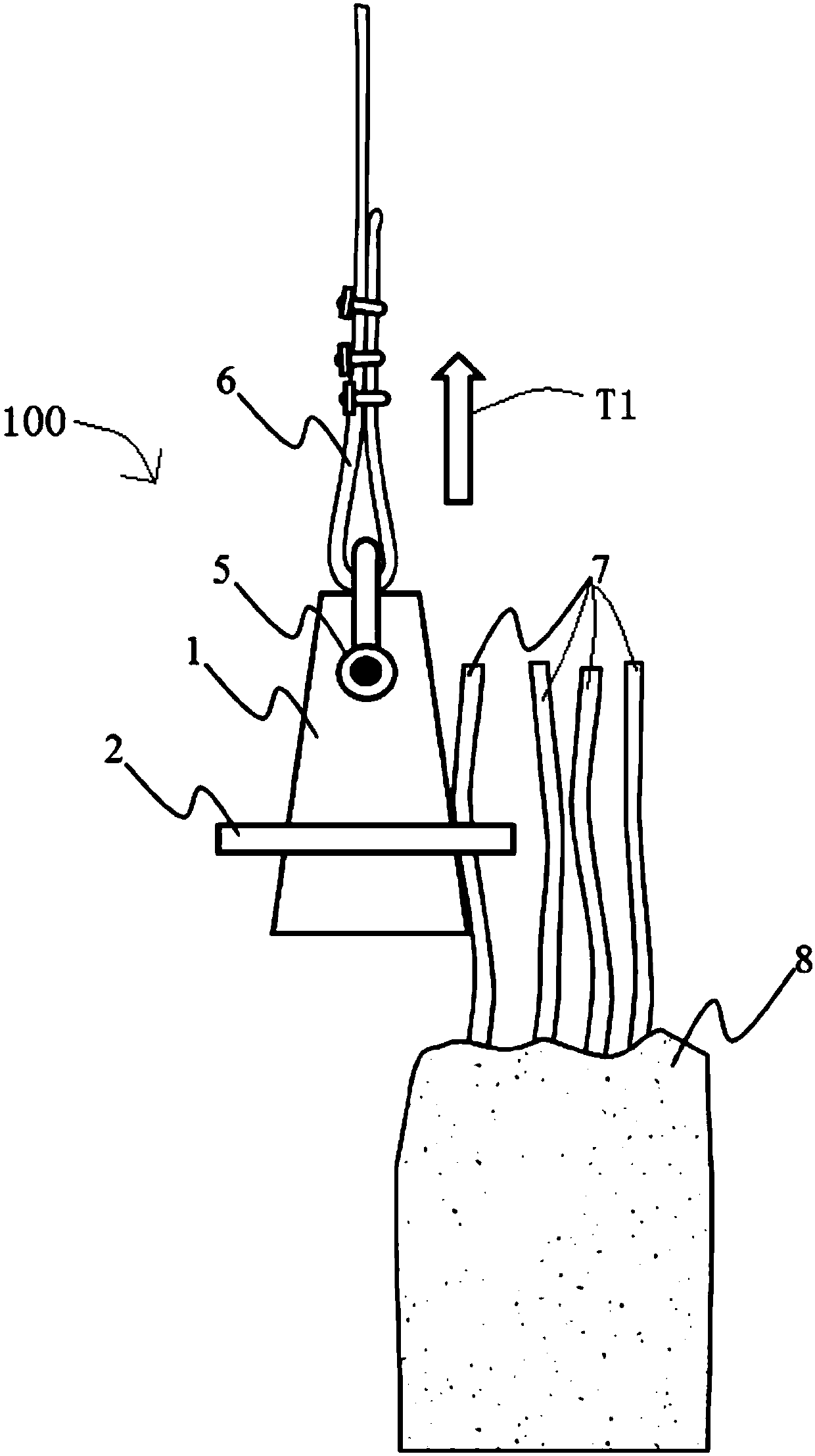
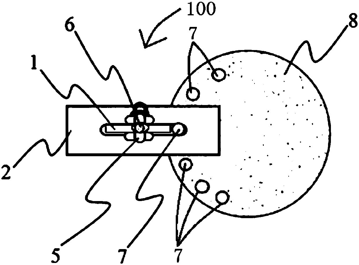
[0029] see figure 1 and figure 2 , which is a clamping device 100 for removing steel bars provided by the present invention. The clamping device 100 for removing steel bars includes a clamping part 2 and a supporting part 1 . The clamping part 2 has a clamping through hole 4 . Part of the support member 1 extends to be inserted into the clamping through hole 4 .

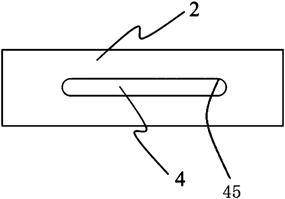
[0030] Please also refer to image 3 , the specific shape and structure of the clamping part 2 only need to be able to abut against the steel bar 7 together with the supporting part 1 . In this embodiment, for the convenience of manufacture, the clamping member 2 is a rectangular plate. In order to improve mechanical strength, the clamping member 2 is a steel plate. The specific shape and size of the clamping through hole 4 provided on the clamping member 2 can be selected according to requirements. The clamping through hole 4 is surrounded by a clamping through hole wall 45 . For the convenience of manufact...

Embodiment 2

[0036] According to needs, the connecting line between a plurality of abutting walls 15 can be set as a triangle, a quadrangle or other polygons. That is, through the cooperation of the multiple abutting walls 15 and the corresponding clamping through-hole walls 45 , multiple steel bars 7 can be clamped.

[0037] Please also refer to Figure 5 and Figure 6 , in the present embodiment, the two abutting walls 15 are arranged transversely facing away from each other, and the two corresponding steel bars 7 can be respectively abutted on the clamping through-hole wall 45 of the clamping member 2, so that Realize the clamping of two steel bars 7 at the same time. That is, if Figure 1 to Figure 3 Corresponding steel bars 7 can be clamped on both sides of the left and right sides.

[0038] The clamping device 100 for pulling out steel bars is suitable for clamping various types and shapes of steel bars 7 . In particular, when the steel bar 7 is a steel bar embedded in a buildin...

Embodiment 3

[0040] see Figure 7 , The invention provides a method for pulling out steel bars. In the method for removing steel bars, the steel bar 7 is clamped by using the clamping device 100 for removing steel bars as described above. Specifically, described steel bar extraction method comprises the following steps:

[0041]S101: Provide a clamping part 2. The clamping part 2 has a clamping through hole 4 . The clamping through hole 4 is surrounded by a clamping through hole wall 45;

[0042] S102: Make the steel bar 7 extend into the clamping through hole 4, and set up facing or in contact with the clamping through hole wall 45;

[0043] S103: Provide a support 1 . A part of the support member 1 is inserted into the clamping through hole 4 . The support 1 has an abutment wall 15 . The abutting wall 15 is made to abut against the steel bar 7 , and at the same time, the steel bar 7 is urged to abut against the clamping through-hole wall 45 .

[0044] In step S102, according to t...


PUM


Abstract

The invention discloses a clamping device for steel bar pulling-out and a steel bar pulling-out method. The clamping device for steel bar pulling-out comprises a clamping part and a supporting part. The clamping part is provided with a clamping through hole which is defined by a clamping through hole wall. A part of the supporting part extends to be inserted into the clamping through hole. The supporting part is provided with abutting walls which directly face the clamping through hole wall, and the abutting walls and the clamping through hole wall can be used for jointly abutting against a steel bar in the radical direction of the clamping through hole. The clamping device for steel bar pulling-out is simplified in structure and stable in clamping.

Description

technical field [0001] The invention relates to construction equipment, in particular to a clamping device and a method for pulling out steel bars. Background technique [0002] In production and life, it is often necessary to use corresponding clamping devices to achieve clamping operations on corresponding items. In particular, with the accelerated development of China's urbanization, urban construction land is becoming more and more tense, and more and more underground structures and foundations remain underground after the superstructures of existing buildings (structures) are dismantled. During subsequent construction, these remaining old reinforced concrete structures, old pile foundations and other obstacles often need to be removed. These underground obstacles have become a thorny problem in underground engineering construction. The existence of underground obstacles often leads to rerouting, relocation or redesign, resulting in half-way construction, which directly...

Claims


Application Information

Patent Timeline
Patent Type & Authority Applications(China)
IPC IPC(8): E04G23/08
CPCE04G23/082
Inventor 胡晓虎丁勇春孙浩高际雅次
Owner 上海开普天岩土科技集团有限公司
Why Eureka
Try Eureka