
Flesh separating machine

A technology of bone and meat separation and separation cylinder, which is applied in the field of bone and meat separators, can solve the problems of inconvenient manual collection, high cost, and low efficiency, achieve high bone and meat separation rate, and improve the service life

Active Publication Date: 2018-02-13
SUNBY MACHINERY CO LTD
View PDF5 Cites 10 Cited by
  • Summary
  • Abstract
  • Description
  • Claims
  • Application Information

AI Technical Summary

Problems solved by technology

[0002] The raw materials currently separated by the bone and meat separator are mainly the necks of poultry and the skeletons after deboning. After these raw materials are preliminarily processed and harvested, there will be a large amount of meat remaining on them. Manual collection is inconvenient, and the efficiency is low and the cost is high. In order to collect these The meat on the raw material with low cost immediately produces a bone and meat separator, which can separate the bone and meat after crushing and extrusion, saving time and effort, and can obtain high economic benefits
However, the separation part of the existing bone and meat separator is easy to wear, which leads to the deterioration of the separation effect of the bone and flesh, and cannot maintain a high and stable separation effect of the bone and flesh, and the weight of the separation part is relatively large, which is not easy to replace, which reduces the cost of the bone and flesh separator. service life

Method used


Image

  • Flesh separating machine
  • Flesh separating machine
  • Flesh separating machine

Examples


Embodiment 1

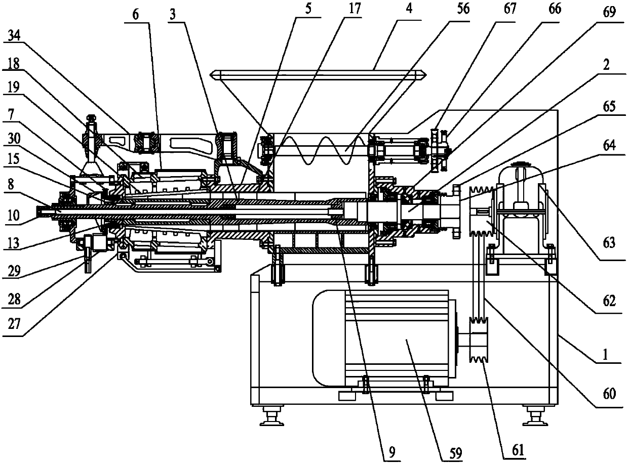
[0050] This embodiment provides a bone and meat separator, such as figure 1 As shown, it includes a frame 1, a drive mechanism, a transmission shaft 2, a screw shaft 3, a feed hopper 4, a pressurization part 5 and a flesh and bone separation part 6, and the feed hopper 4 is arranged on the frame 1, and the feed hopper 4 The outlet is communicated with the inlet of the supercharging part 5, the outlet of the supercharging part 5 is connected with the inlet of the bone-meat separation part 6, one end of the transmission shaft 2 is connected with the output end of the driving mechanism, and one end of the screw shaft 3 is sleeved on the other end of the transmission shaft 1 and can be opposite to each other. As the transmission shaft 2 moves, one end of the screw shaft 2 in this embodiment is provided with an inner triangular hole, and the end connecting the transmission shaft 2 and the screw shaft 3 is set as an outer triangle matching the inner triangular hole; Below the feedin...


PUM


Abstract

The invention discloses a flesh separating machine which comprises a machine frame, a driving mechanism, a transmission shaft, a screw shaft, a feeding hopper, a pressurizing part and a flesh separating part. The separating screw shaft part is a conical screw shaft, and the flesh separating part is also a conical component coaxially sleeved on the outer periphery of the separating screw shaft; theinner wall of the separation screw shaft is provided with a clearance fit with the outer wall of the separation screw shaft part; the side wall of one end of the separation part near the pressurizingpart is provided with a clearance gap; a control valve is arranged on the outer periphery of the front end of the separation screw shaft part and the front end of the separation screw shaft part; a slag discharge gap is arranged; the screw shaft is a hollow screw shaft which is internally provided with an adjusting rod; one end of the transmission shaft is fixedly provided with a connecting part.One end of the adjusting rod is screwed with the connecting part, and the other end of the adjusting rod extends out of the screw shaft and extends out of the flesh separating part. The flesh separating machine makes the inner wall of the flesh separation part and the outer wall of the spiral shaft always in a relatively stable gap fit state, which improves the service life.

Description

technical field [0001] The invention relates to food processing machinery, in particular to a bone and meat separator. Background technique [0002] The raw materials currently separated by the bone and meat separator are mainly the necks of poultry and the skeletons after deboning. After these raw materials are preliminarily processed and harvested, there will be a large amount of meat remaining on them. Manual collection is inconvenient, and the efficiency is low and the cost is high. In order to collect these The meat on the raw material with lower cost immediately produces a bone and meat separator, which is crushed and squeezed to separate the bones from the meat, saving time and effort, and can obtain high economic benefits. However, the separation part of the existing bone and meat separator is easy to wear, which leads to the deterioration of the separation effect of the bone and flesh, and cannot maintain a high and stable separation effect of the bone and flesh, an...

Claims


Application Information

Patent Timeline
IPC IPC(8): A22C17/00A22C21/00A22B5/00
CPCA22B5/0035A22C17/004A22C21/0069A22C17/04
Inventor 张百春张天阳张天放
Owner SUNBY MACHINERY CO LTD
Learn More