
Movable type tunnel monitoring equipment with fire extinguishing function

A tunnel monitoring and mobile technology, used in fire rescue, fire alarms, instruments, etc., can solve problems such as hindering the progress of rescue, increasing cost input, monitoring equipment damage, etc., to save cost investment and expand monitoring range. Effect

Inactive Publication Date: 2018-02-16
苏州奥柯图葳机电科技有限公司
View PDF0 Cites 11 Cited by
  • Summary
  • Abstract
  • Description
  • Claims
  • Application Information

AI Technical Summary

Problems solved by technology

[0002] Highway tunnels are located in areas away from the city center or in mountainous areas with complex terrain. Once an accident occurs, the high temperature and closed environment are not conducive to the diffusion of smoke and flammable gases. The visibility in the tunnel is reduced, and the specific cause of the fire cannot be judged. As a result, the rescue plan was delayed and it was not easy to rescue. On the other hand, the remote location and complex on-site environment hindered the progress of basic rescue. The fire-fighting facilities were not in place, and the traffic paralysis in the tunnel increased the difficulty of rescue.
[0003] Although the current highway tunnels also have some equipment for fire monitoring, there are still some problems in the actual use process. Most of these monitoring equipment are fixedly installed on the inner wall of the tunnel, and fixed installation means that a large number of Monitoring equipment can ensure the monitoring of the tunnel, which greatly increases the cost investment. In addition, once a fire or explosion occurs, it is easy to cause damage to the monitoring equipment. Moreover, many current monitoring equipment only have monitoring functions, and tunnel fires still rely on firefighters. However, the complex environment of the tunnel often hinders the rescue, which leads to huge economic losses. If the above problems cannot be solved, the practicability and functionality of the detection equipment will be greatly reduced

Method used


Image

  • Movable type tunnel monitoring equipment with fire extinguishing function
  • Movable type tunnel monitoring equipment with fire extinguishing function
  • Movable type tunnel monitoring equipment with fire extinguishing function

Examples


Embodiment Construction

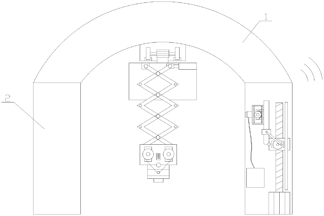
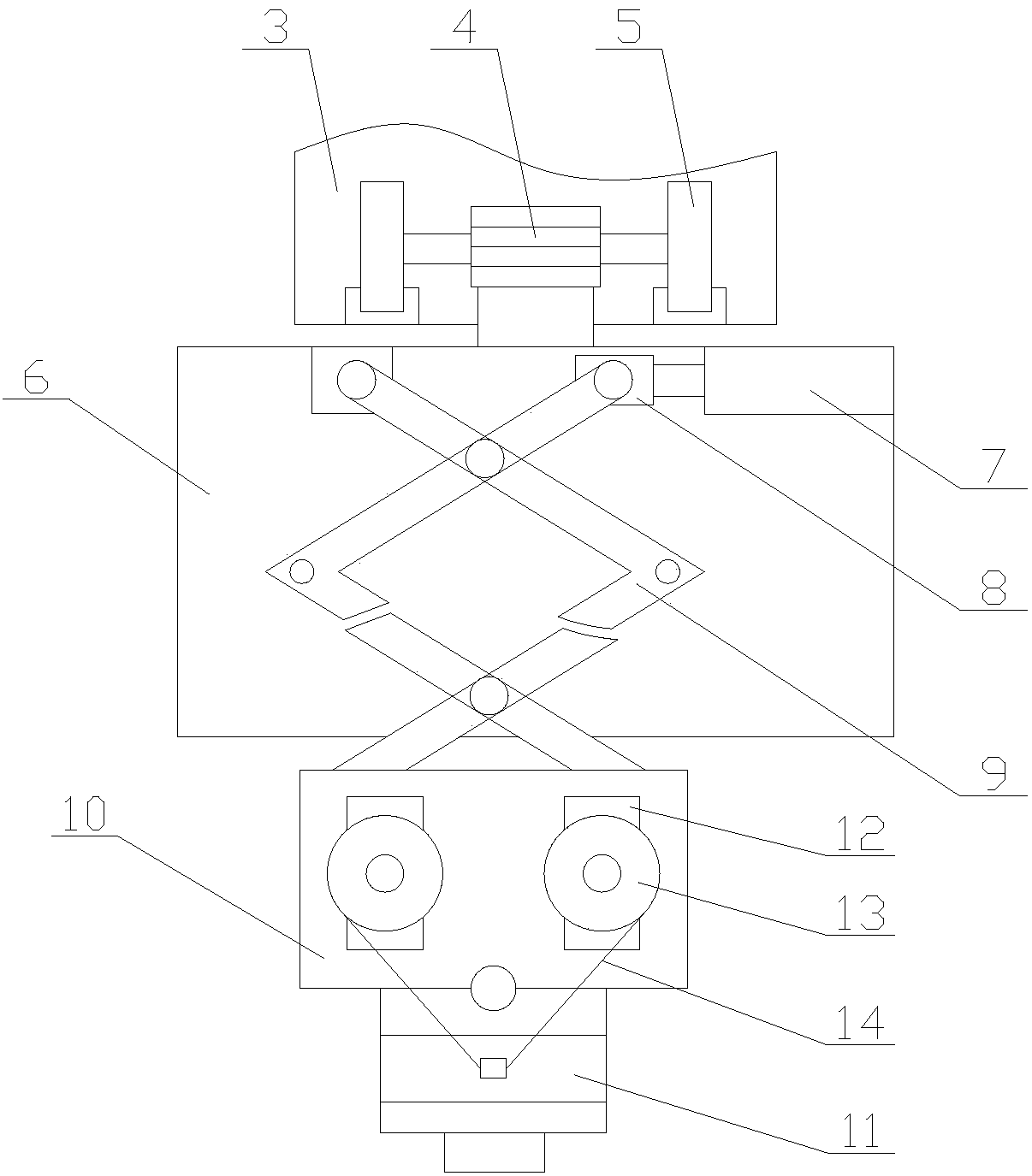
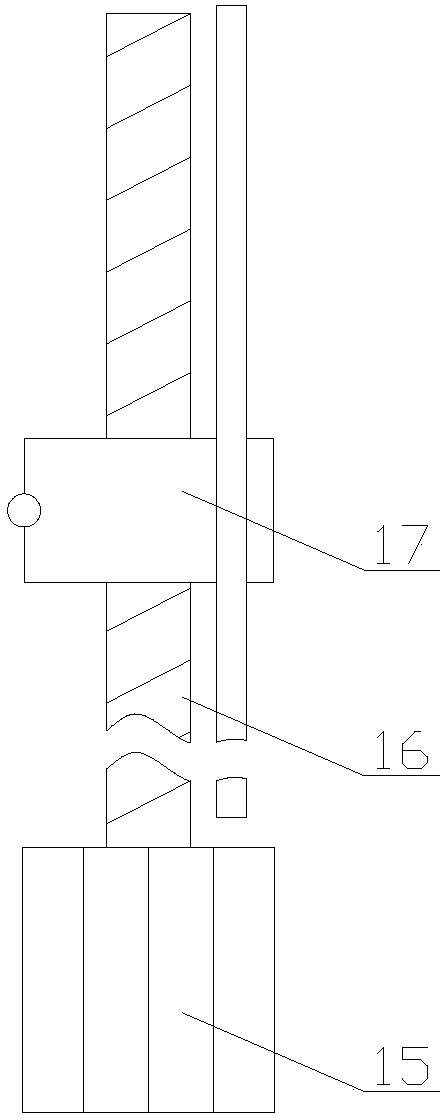
[0029] The present invention is described in further detail now in conjunction with accompanying drawing. These drawings are all simplified schematic diagrams, which only illustrate the basic structure of the present invention in a schematic manner, so they only show the configurations related to the present invention.

[0030] like Figure 1-Figure 5As shown, a mobile tunnel monitoring device with fire extinguishing function includes a roof 1, two support columns 2, a monitoring mechanism and a fire extinguishing mechanism. 1 is symmetrical, the monitoring mechanism is arranged under the top plate 1 and between the two supporting columns 2, and the fire extinguishing mechanism is arranged inside the supporting columns 2;

[0031] The monitoring mechanism includes a mobile assembly and a telescopic assembly, the telescopic assembly is arranged inside the mobile assembly, and the mobile assembly is connected to the telescopic assembly by transmission;

[0032] The telescopic ...


PUM


Abstract

The invention relates to a mobile tunnel monitoring device with fire extinguishing function, which includes a top plate, two support columns, a monitoring mechanism and a fire extinguishing mechanism. frame, lifting plate and fire detector, and the fire extinguishing mechanism includes a lifting component, a swing component and a fire extinguishing component. In the mobile tunnel monitoring equipment with fire extinguishing function, through the monitoring mechanism, only a small number of fire detectors can be used to monitor the entire tunnel, which saves cost investment. In addition, the fire detection is driven by the telescopic frame The device retracts into the interior of the shell, which can play a protective role. Through the fire extinguishing mechanism, the fire extinguishing response is faster and safer, and the economic loss can be reduced as much as possible. It is safe and reliable. Through these, the practicality of tunnel monitoring equipment is improved. sex and reliability.

Description

technical field [0001] The invention relates to the field of tunnel monitoring equipment, in particular to a mobile tunnel monitoring equipment with fire extinguishing function. Background technique [0002] Highway tunnels are located in areas away from the city center or in mountainous areas with complex terrain. Once an accident occurs, the high temperature and closed environment are not conducive to the diffusion of smoke and flammable gases. The visibility in the tunnel is reduced, and the specific cause of the fire cannot be judged. As a result, the rescue plan was delayed and it was not easy to rescue. On the other hand, the remote location and complex on-site environment hindered the progress of basic rescue. The fire-fighting facilities were not in place, and the traffic paralysis in the tunnel increased the difficulty of rescue. [0003] Although the current highway tunnels also have some equipment for fire monitoring, there are still some problems in the actual us...

Claims


Application Information

Patent Timeline
IPC IPC(8): A62C3/02A62C31/00A62C31/28G08B17/00
CPCA62C3/0221A62C31/005A62C31/28G08B17/00
Inventor 俞桂英
Owner 苏州奥柯图葳机电科技有限公司
Learn More