
Electric automobile charging system and charging control system

A technology for electric vehicles and charging systems, applied in electric vehicle charging technology, electric vehicles, charging stations, etc., can solve the problems of difficult circuit design and high cost, and achieve improved redundancy and reliability, low cost, and circuit design. simple effect

Active Publication Date: 2018-02-16
XJ POWER CO LTD +3
View PDF7 Cites 1 Cited by
  • Summary
  • Abstract
  • Description
  • Claims
  • Application Information

AI Technical Summary

Problems solved by technology

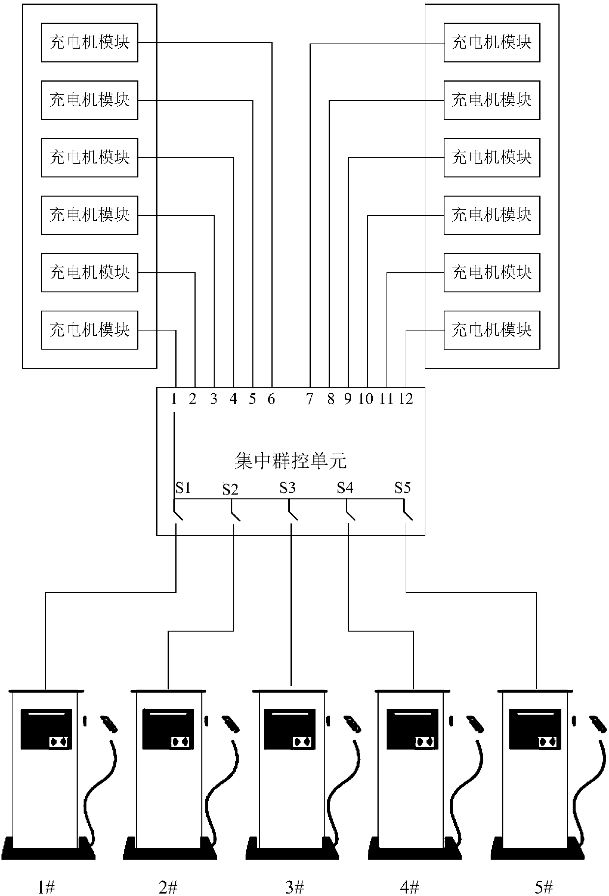
[0005] The purpose of the present invention is to provide an electric vehicle charging system and a charging control system, which are used to solve the problem that the charging piles in the prior art are all connected to the centralized group control unit, resulting in difficult circuit design and high cost.

Method used


Image

  • Electric automobile charging system and charging control system
  • Electric automobile charging system and charging control system
  • Electric automobile charging system and charging control system

Examples


Embodiment 1

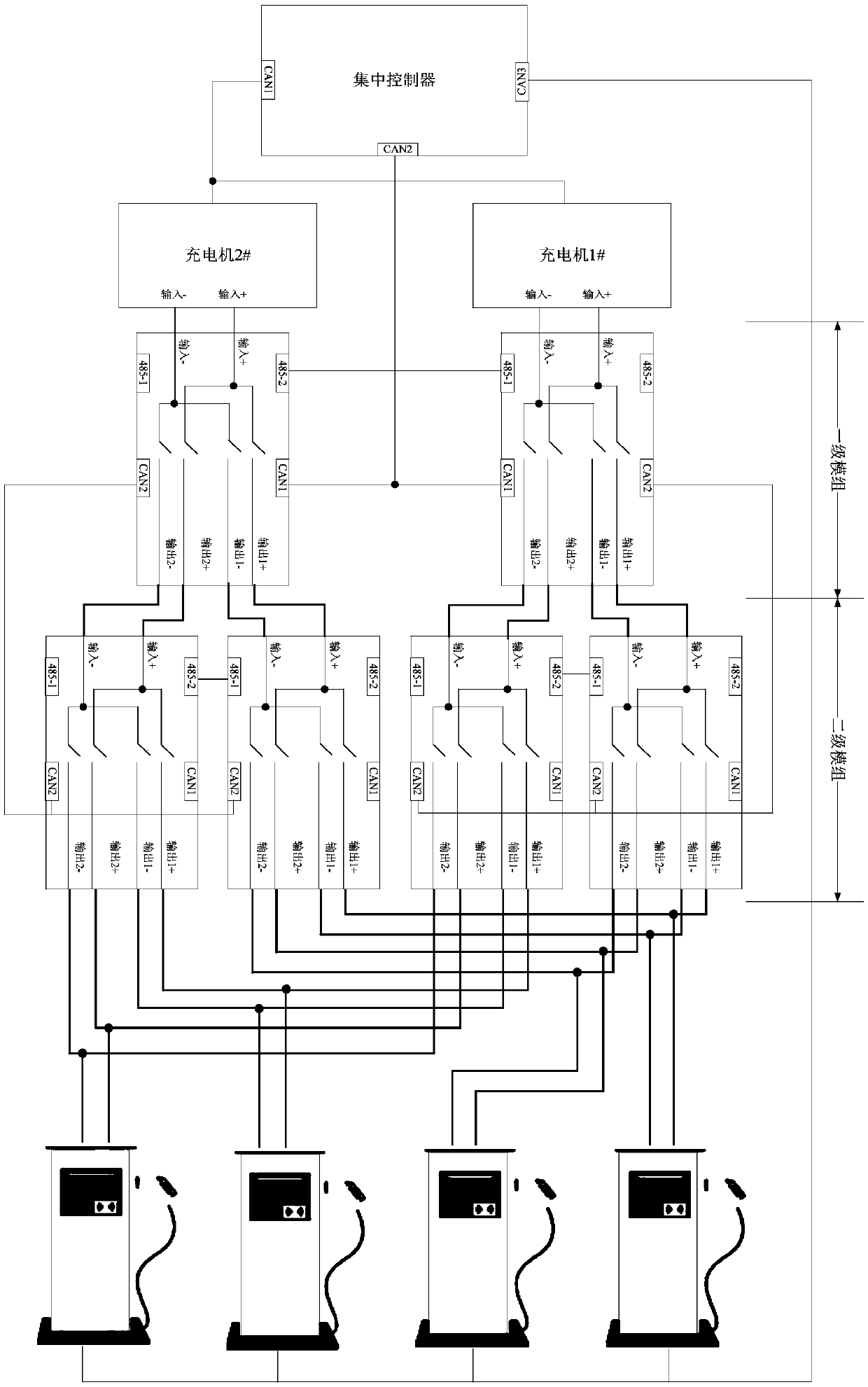
[0026] An electric vehicle charging system of the present invention includes a charging control system, a charger, and a charging pile. Among them, the charging control system includes a controller and a basic module unit for connecting the charger and the charging pile. The basic module unit has at least two levels. Each charger is connected to the charging pile through the basic module unit. The basic module unit of the previous level and the basic module unit of the subsequent level are connected in a tree shape. Each basic module unit includes one Input interface, two output interfaces, input interface strobes to connect two output interfaces. The basic module unit of the last stage of each charger is connected to all charging piles, and the last stage refers to the basic module unit whose output interface is not connected to any basic module unit. The controller is connected to at least two chargers, and each charger is connected to the charging pile through at least two-...

Embodiment 2

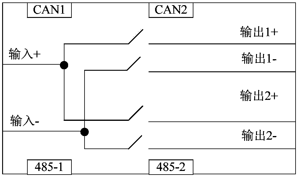
[0031] Such as image 3 The basic module unit shown is provided with 1 input interface, 2 output interfaces, 2 CAN communication interfaces, and 2 485 communication interfaces, and a switch is connected between the data interface and the output interface, and the switch is turned on. And shut-off is controlled by a centralized controller. Centralized controller such as Figure 4 As shown, there are 3 CAN communication interfaces, which are respectively responsible for communicating with the charging pile, the charger, and the basic module.

[0032] The electric vehicle charging system mainly composed of the above-mentioned basic module units and centralized controllers such as figure 2 As shown, the centralized controller is connected to charger 1# and charger 2#, namely charger 1 and charger 2, through the communication interface CAN1, and both chargers are connected through their respective primary and secondary modules Charging pile, where the first-level module corresponding...


PUM


Abstract

The invention relates to an electric automobile charging system and a charging control system. Basic module units with tree structures are arranged between a charger and a charging pile to connect thecharger with the charging pile; at least two stages of basic module units are arranged; and a controller performs matching between the charger and the charging pile by controlling the on-off of the basic module units and gating a branch circuit for connecting the charger with the charging pile. The circuit design is simple; the circuit design cost is low; any charger can supply power to any charging pile; and redundancy and reliability of the charging system and the charging control system are improved.

Description

Technical field [0001] The invention belongs to the technical field of electric vehicle charging, and specifically relates to an electric vehicle charging system and a charging control system. Background technique [0002] With the improvement of the development of electric vehicles and the introduction of the country's technical support policies for new energy vehicles, the blueprint for the quantitative production of electric vehicles has gradually become clear. The development of electric vehicles in the future is bound to be a major trend of the automotive industry. Electric vehicle charging station is a very important part of electric vehicle supporting products. [0003] Compared with the integrated charging pile, the centralized control solves the problem of heat dissipation and IP protection of the charger, and can reduce the area of ​​the charging pile. The construction of the charging station gradually separates from the integrated charger to the pile machine, and the ce...

Claims


Application Information

Patent Timeline
Patent Type & Authority Applications(China)
IPC IPC(8): B60L11/18G07F15/00G06Q50/06
CPCB60L53/30G06Q50/06G07F15/005Y02T10/70Y02T10/7072Y02T90/12
Inventor 刘超张臻陈天锦曹智慧韩海伦马骏陈世锋高鹏余文杰李正力于浩然李新元陈常曦吕海超王翼吴道阳刘振威
Owner XJ POWER CO LTD
Learn More