
Tap water flow control system

A water flow control and tap water technology, applied in water supply pipeline systems, water supply devices, water supply devices, etc., can solve problems such as unstable water flow and water cut-off for high-rise residents

Pending Publication Date: 2018-02-16
XINGAN ANHUI ELECTRIC LTD BY SHARE LTD
View PDF7 Cites 2 Cited by
  • Summary
  • Abstract
  • Description
  • Claims
  • Application Information

AI Technical Summary

Problems solved by technology

On the basis of the pressure of the municipal pipe network, the water supply is directly superimposed to save energy, and it also has many advantages such as fully enclosed, pollution-free, small footprint, quick installation, reliable operation, and convenient maintenance. The current water supply equipment is in the water supply During the process, the water flow is often unstable, sometimes large and sometimes small, especially during peak water consumption hours, water cutoffs for high-rise residents often occur

Method used


Image

  • Tap water flow control system
  • Tap water flow control system

Examples


Embodiment 1

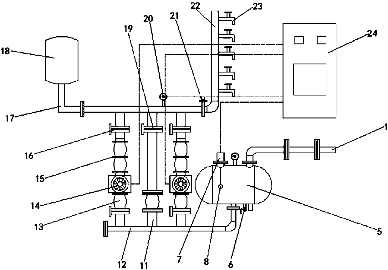
[0012] refer to figure 1 , a tap water flow control system, including a steady flow regulator (5), a frequency conversion water supply control cabinet (24), a water pump (14), a remote pressure gauge (20), the steady flow regulator (5) and the water inlet pipe (11) connected, the upper end of the steady flow regulator (5) is equipped with a vacuum suppressor (7) and a pressure gauge, and the inside of the steady flow regulator (5) is equipped with an anhydrous shutdown liquid level float (8), and the non-water shutdown liquid level float (8) is connected to the vacuum suppressor (7) through a connecting line, and the lower end of the steady flow regulator (5) is provided with a blowdown valve (6), and the steady flow The lower end of the regulator (5) is also provided with a fourth connecting pipe, and the end of the first connecting pipe far away from the steady flow regulator (5) is provided with a second connecting pipe (12), and the second connecting pipe (12) There are t...

Embodiment 2

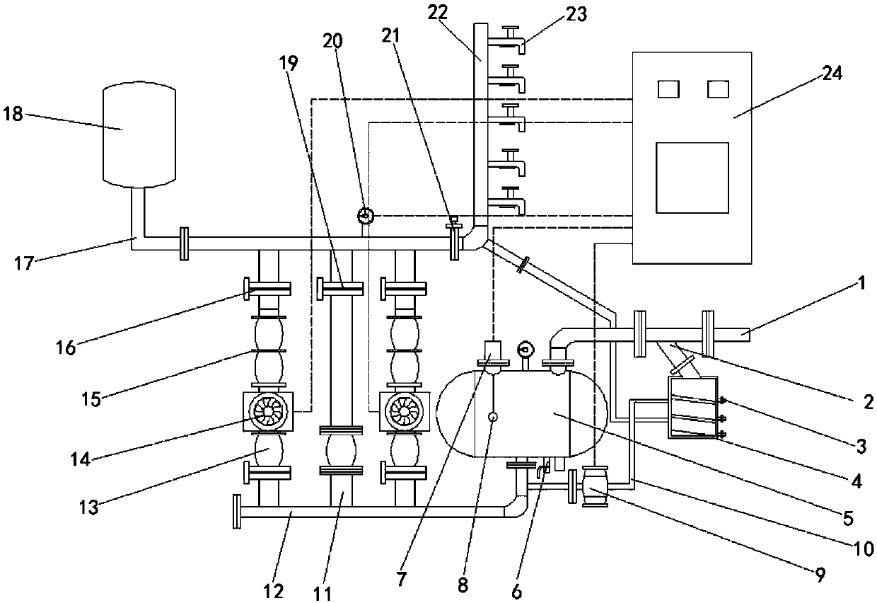
[0015] refer to figure 2 , a tap water flow control system, the application in non-negative pressure frequency conversion water supply equipment, specifically includes a water inlet pipe 1, two control valves are installed on the water inlet pipe 1, and a water extraction pipe is installed on the water inlet pipe 1 between the two control valves. The water pipe 2 and the end of the water intake pipe 2 away from the water inlet pipe 1 are connected with a water intake tank 4. The inside of the water intake tank 4 is provided with three parallel inclined plates from top to bottom. One end of the corresponding water outlet sampling pipe 3 and the water inlet pipe 1 is connected with a steady flow regulator 5, the upper end of the steady flow regulator 5 is respectively equipped with a vacuum suppressor 7 and a pressure gauge, and the inside of the steady flow regulator 5 is provided with an anhydrous Shutdown liquid level float 8, and anhydrous shutdown liquid level float 8 is c...


PUM


Abstract

The invention discloses a tap water flow control system. The tap water flow control system includes a steady flow adjustor, a frequency-variable water supply control cabinet, second water pumps, and atransmissible pressure gauge; the steady flow adjustor communicates with a water inlet pipe; a vacuum suppressor and a pressure meter are arranged on an upper end of the steady flow adjustor; a waterless stopping liquid level floating ball is arranged in the steady flow adjustor, and is connected to a vacuum suppressor through a connection line; the second water pumps, the vacuum suppressor, andthe transmissible pressure gauge are connected to the external frequency-variable water supply control cabinet through wires; and when water is coming or cut off, a liquid level detector can feed a signal back to a frequency-variable controller; the water pump is automatically started or stopped so as to protect a water pump set. When the water flow is small at nighttime and the pressure of a tapwater pipe cannot meet a demand, an air pressure tank can store and release energy so as to prevent frequent start of the water pumps, and in this way, the stability of water supply can be ensured, and a good energy-saving and emission reduction effect can be achieved.

Description

technical field [0001] The invention relates to the technical field of water supply, in particular to a tap water flow control system. Background technique [0002] At present, the non-negative pressure frequency conversion water supply equipment uses the municipal pipe network as the water source, making full use of the original pressure of the municipal pipe network to form a closed continuous relay pressurized water supply method, which has good energy saving effect and no secondary pollution of water quality. Development and extension of constant pressure water supply equipment. On the basis of the pressure of the municipal pipe network, the water supply is directly superimposed to save energy, and it also has many advantages such as fully enclosed, pollution-free, small footprint, quick installation, reliable operation, and convenient maintenance. The current water supply equipment is in the water supply During the process, the water flow is often unstable, sometimes l...

Claims


Application Information

Patent Timeline
Patent Type & Authority Applications(China)
IPC IPC(8): E03B1/02E03B7/07E03B11/16
CPCE03B1/02E03B7/07E03B7/071E03B7/072E03B7/075E03B7/077E03B7/078E03B11/10
Inventor 钱忠宝潘志强廉守英
Owner XINGAN ANHUI ELECTRIC LTD BY SHARE LTD
Learn More