Heat dissipation device of automobile engine

A technology for automobile engine and heat dissipation device, which is applied to the cooling of engine components, machines/engines, and engines, etc., can solve the problems of lowering the temperature of the coolant in the radiator, complicated installation and disassembly of the heat dissipation device, and poor heat dissipation effect, and achieves heat dissipation. The effect is better, the installation and disassembly are convenient and fast, and the heat dissipation effect is good.

Inactive Publication Date: 2018-02-16
陈宏
View PDF0 Cites 3 Cited by
  • Summary
  • Abstract
  • Description
  • Claims
  • Application Information

AI Technical Summary

Problems solved by technology

Most of the existing heat dissipation devices use the engine fan to suck in the wind through the radiator, fan, engine, and then be discharged from the machine, which not only reduces the temperature of the coolant in the radiator, but also takes away the heat of the engine when the wind flows through the engine. , but the heat dissipation effect is not good, and the fan consumes too much energy. In addition, the existing heat dissipation device is cumbersome to install and disassemble, and it is not easy to maintain

Method used


Image

  • Heat dissipation device of automobile engine
  • Heat dissipation device of automobile engine
  • Heat dissipation device of automobile engine

Examples


Embodiment Construction

[0018] The following will clearly and completely describe the technical solutions in the embodiments of the present invention with reference to the accompanying drawings in the embodiments of the present invention. Obviously, the described embodiments are only some, not all, embodiments of the present invention. All other embodiments obtained by persons of ordinary skill in the art based on the embodiments of the present invention belong to the protection scope of the present invention.

[0019] According to an embodiment of the present invention, a cooling device for an automobile engine is provided.

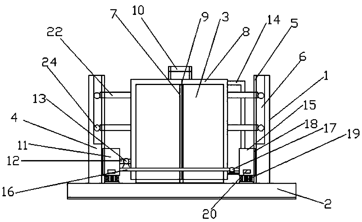
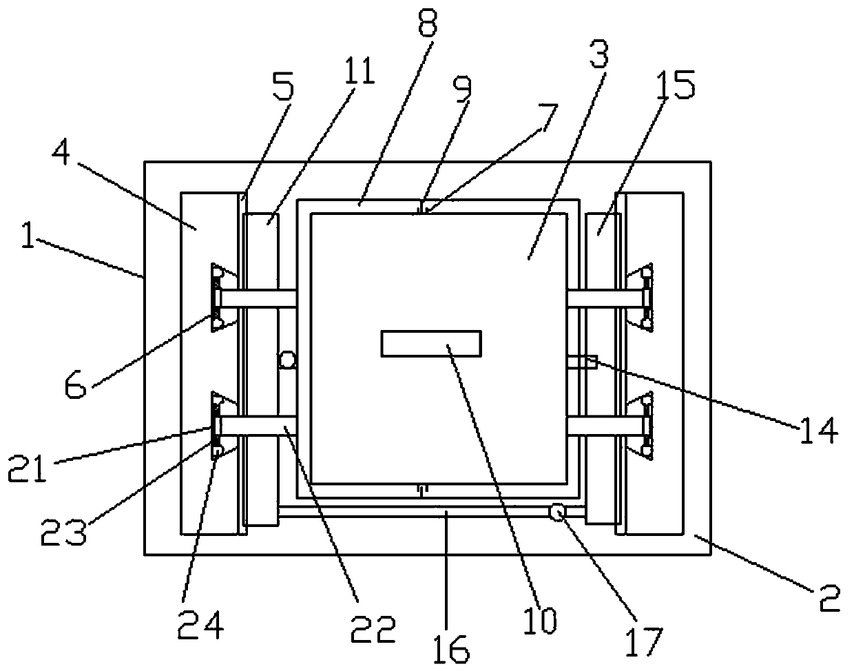
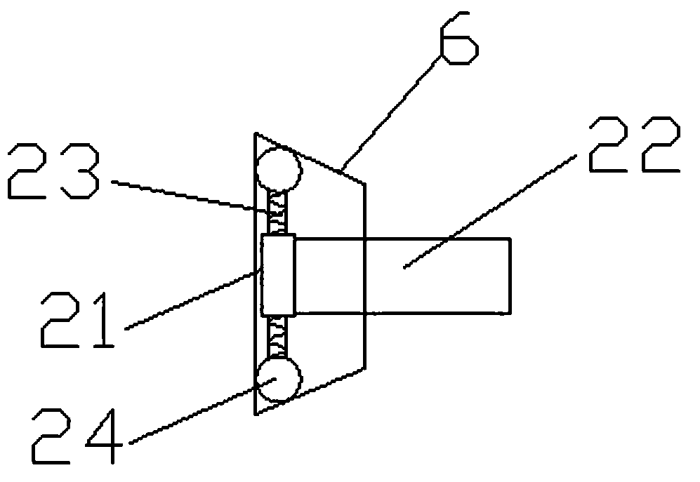
[0020] Such as Figure 1-3 As shown, the automobile engine cooling device of the embodiment of the present invention includes a housing 1, a base 2 is provided at the bottom of the housing 1, a shock absorbing plate is provided at the bottom of the base 2, an engine 3 is provided at the center of the top of the base 2, and an engine 3 is provided at the center of the base 2. 2...


PUM


Abstract

The invention discloses a heat dissipation device for an automobile engine, which comprises a casing, a base is arranged at the bottom of the casing, an engine is arranged at the center of the top of the base, a fixing plate is arranged on both sides of the top of the base, and a slide rail is arranged on one side of the fixing plate. There are several installation grooves on the fixed plate, chute on the side of the engine, a heat dissipation layer on the top of the engine, slide bars on the inside of the heat dissipation layer, a water tank at the bottom of one side of the heat dissipation layer, and an inlet on one side of the water tank. Water pipe, water pump 1 is provided on the water inlet pipe, water outlet pipe is provided on the top of the other side of the heat dissipation layer, water tank 2 is provided at one end of the water outlet pipe, circulating water pipe is provided on the side of water tank 2, water pump 2, water tank 1 and water tank are provided on the circulating water pipe Two other sides are provided with sliders, water tank one and water tank two bottoms are all provided with damping springs, water tank one and water tank two are all provided with condensers, and both sides of the cooling layer are provided with several sets of mounting parts. The device has simple structure, good heat dissipation effect, convenient installation and disassembly, and convenient maintenance.

Description

technical field [0001] The invention relates to the technical field of heat dissipation equipment, in particular to a heat dissipation device for an automobile engine. Background technique [0002] The car engine is an important part of the car. The engine will generate a lot of heat when it is working normally. If the heat cannot be removed in time, it will cause the engine to stall, explode the cylinder, etc., so it is necessary to use a cooling device. Most of the existing heat dissipation devices use the engine fan to suck in the wind through the radiator, fan, engine, and then be discharged from the machine, which not only reduces the temperature of the coolant in the radiator, but also takes away the heat of the engine when the wind flows through the engine. , but the heat dissipation effect is not good, and the fan consumes too much energy. In addition, the installation and disassembly of the existing heat dissipation device is cumbersome and inconvenient for maintena...

Claims


Application Information

Patent Timeline
Patent Type & Authority Applications(China)
IPC IPC(8): F01P11/00F01P3/18F01P5/10F16F15/08
CPCF01P11/00F01P3/18F01P5/10F01P2005/105F01P2050/22F16F15/08
Inventor 陈宏王昕
Owner 陈宏
Why Eureka
Try Eureka