
Power facility temporary mounting rack convenient for demounting and mounting

A technology for easy disassembly and assembly of power facilities, applied in the direction of lifting frames, lifting devices, mechanical equipment, etc., can solve the problems of not being able to cope with different erection heights, inconvenient disassembly and carrying, and inconvenient use, etc., to achieve Simple structure, easy disassembly and carrying, and convenient operation

Inactive Publication Date: 2018-02-16
CHENGDU ZHIQI TECH
View PDF0 Cites 29 Cited by
  • Summary
  • Abstract
  • Description
  • Claims
  • Application Information

AI Technical Summary

Problems solved by technology

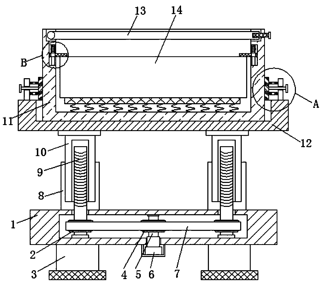
[0002] In the process of temporary construction of power facilities, it is often necessary to use temporary installation frames to set up and place cables. For traditional temporary installation frames, welding or fixed connections are used between parts to make the overall structure stable. However, this integrated The traditional temporary installation frame is large in size, inconvenient to disassemble and carry, and cannot cope with different erection heights for its own height adjustment. It is inconvenient to use, which requires a convenient disassembly Temporary installation frame for electrical facilities

Method used


Image

  • Power facility temporary mounting rack convenient for demounting and mounting
  • Power facility temporary mounting rack convenient for demounting and mounting
  • Power facility temporary mounting rack convenient for demounting and mounting

Examples


Embodiment Construction

[0016] The following will clearly and completely describe the technical solutions in the embodiments of the present invention with reference to the accompanying drawings in the embodiments of the present invention. Obviously, the described embodiments are only some, not all, embodiments of the present invention.

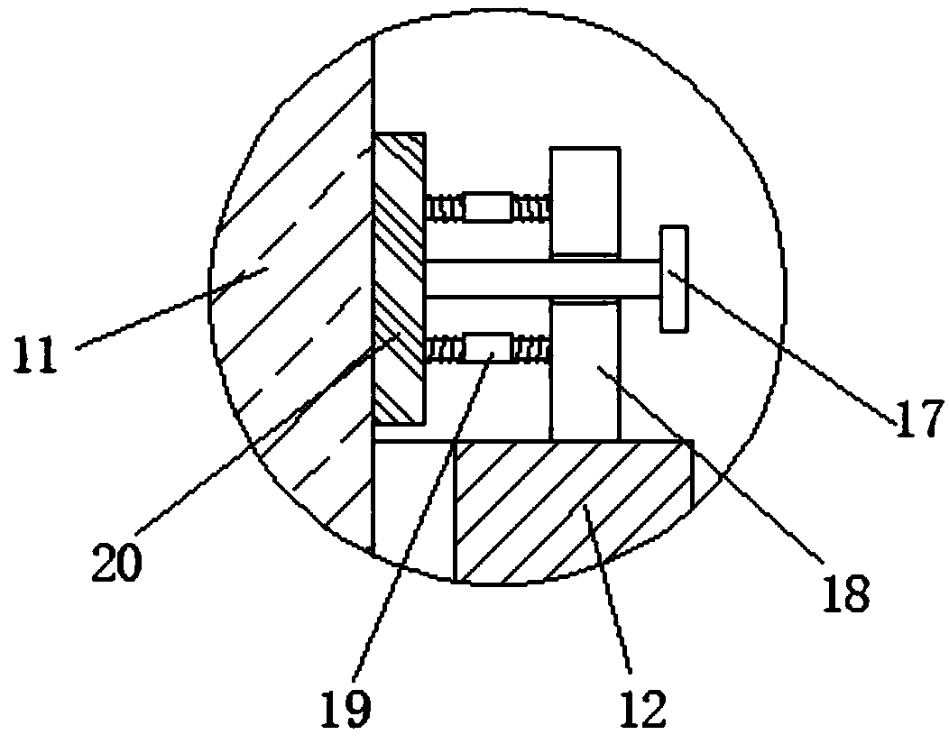
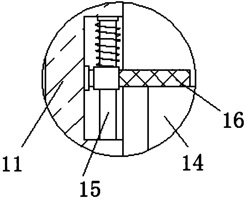
[0017] refer to Figure 1-3 , a temporary installation frame for power facilities that is convenient for disassembly and assembly, including a base 1, two first hollow columns 8 are fixedly connected to the upper end of the base 1, and a second hollow column 10 is slidingly sleeved in the two first hollow columns 8, the second The second hollow column 10 and the first hollow column 8 are connected by a sliding socket, the second hollow column 10 can slide in the first hollow column 8, and the upper ends of the two second hollow columns 10 are fixedly connected with a placement plate 12 and a base 1 The interior of the base 1 is provided with a storage slot, the lower...


PUM


Abstract

The invention discloses a convenient disassembly and assembly temporary installation frame for electric facilities, including a base, the upper end of the base is fixedly connected with two first hollow columns, and a second hollow column is slidingly sleeved in the two first hollow columns , the upper ends of the two second hollow columns are fixedly connected with a placement plate, the inside of the base is provided with a storage slot, the lower end of the base is fixedly connected with a driving device, the end of the output shaft of the driving device passes through the storage slot and A rotating rod is fixedly connected, and the upper end of the rotating rod is rotatably connected to the inner top of the storage tank. The first gear is fixedly sleeved on the side wall of the rotating rod, and the inner bottom of the storage tank is rotatably connected with two threads. rods, and the second gears are fixedly sleeved on the side walls of the two threaded rods. The invention has simple structure, convenient operation, can adjust its height according to actual power construction conditions, is convenient to disassemble and carry, and has very good use effect.

Description

technical field [0001] The invention relates to the technical field of electric power construction equipment, in particular to a temporary installation frame for electric power facilities that is convenient for assembly and disassembly. Background technique [0002] In the process of temporary construction of power facilities, it is often necessary to use temporary installation frames to set up and place cables. For traditional temporary installation frames, welding or fixed connections are used between parts to make the overall structure stable. However, this integrated The traditional temporary installation frame is large in size, inconvenient to disassemble and carry, and cannot cope with different erection heights for its own height adjustment. It is inconvenient to use, which requires a convenient disassembly Temporary installation frame for electrical facilities. Contents of the invention [0003] The purpose of the present invention is to solve the shortcomings in ...

Claims


Application Information

Patent Timeline
IPC IPC(8): F16M11/04F16M11/26B66F7/14F16F15/04
CPCF16M11/04B66F7/14F16F15/04F16F2232/08F16F2238/026F16M11/26
Inventor 任苗
Owner CHENGDU ZHIQI TECH
Learn More