
Rotary groove cutting device

A beveling device and rotary cutting technology, used in shearing devices, pipe shearing devices, accessories of shearing machines, etc., can solve the problems of inconvenient operation, low cutting efficiency, cumbersome structure, etc. The effect of slow cutting and improving cutting efficiency

Active Publication Date: 2021-04-02
河南易沃克工业设备有限公司
View PDF4 Cites 3 Cited by
  • Summary
  • Abstract
  • Description
  • Claims
  • Application Information

AI Technical Summary

Problems solved by technology

[0002] With the demand for pipeline installation in various fields, higher requirements are put forward for the quality of pipeline installation. Pipeline installation mainly involves two major processes of cutting and welding. There are currently two cutting methods on the market, one is high temperature cutting; the other is cold cutting. Cutting; high-temperature cutting leads to changes in the material and shape of the pipe directly affect the subsequent welding quality; while cold cutting can meet the cutting and beveling in different environments and ensure the subsequent welding quality, but cold cutting tools currently on the market generally use Split-type cutting and beveling machine, this kind of cutting and beveling machine on the market has a heavy structure, low cutting efficiency, inconvenient operation, short mission life, and cannot meet the requirements of cutting and high-efficiency beveling in the current market. How to develop a brand new one? The rotary beveling machine, which can cut, bevel, install and disassemble with high efficiency, is extremely convenient and fast, and does not require manual operation, which is particularly important

Method used


Image

  • Rotary groove cutting device
  • Rotary groove cutting device
  • Rotary groove cutting device

Examples


Embodiment Construction

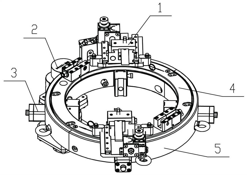
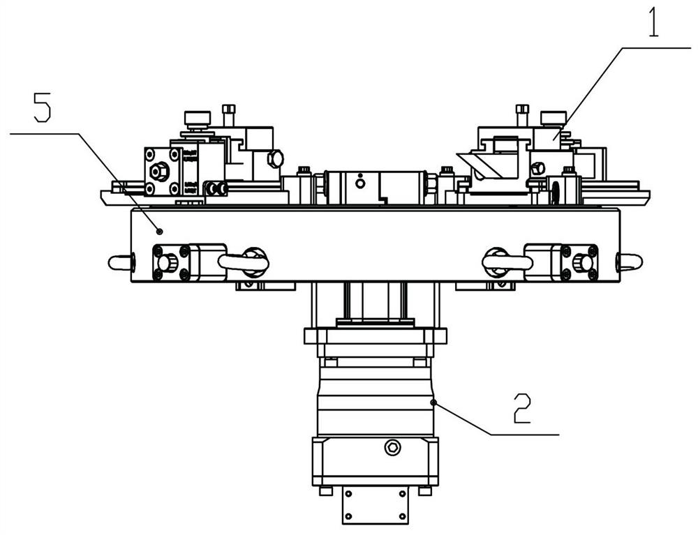
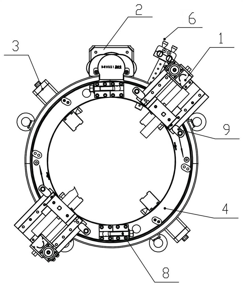
[0046]A rotary cutting beveling device, comprising a feed feed tool holder 1, a speed reduction mechanism 2, a lifting lug bolt 7, a rotation fixing device 8, a tool holder fixing plate 9, a telescopic leg 3, a moving coil device 4, a speed regulating feed The feeding device 6, the ring fixing device 5 and the supporting intelligent control system, the feed tool holder 1 includes a tool holder bottom plate 1-1, and the top side of the tool holder bottom plate 1-1 is provided with a sliding seat 1-6, and the sliding seat 1- 6 is a U-shaped groove structure, the top of the sliding seat 1-6 is provided with a sliding cover 1-4 for sliding connection, the sliding seat 1-6 is provided with a cutter 1-3, and the bottom of the cutter 1-3 passes through the first in the U-shaped groove. The tool holder backing plate 1-22 is fixed, the top of the tool 1-3 is fixed by the compression bolt 1-5 set in the slide cover 1-4, one side of the tool 1-3 is fixed to the side of the U-shaped groove...


PUM


Abstract

The invention discloses a rotary groove cutting device which comprises a feeding knife rest, a speed reducing mechanism, a lifting lug bolt, a rotary fixing device, a tool rest fixing plate, telescopic supporting legs, a movable ring device, a speed regulating feeding device, a fixed ring device and an intelligent control system, wherein the fixed ring device and the movable ring device are assembled together through a plurality of eccentric wheels and concentric wheels, a feeding tool rest is fixed to the moving ring device through the tool rest fixing plate, the speed reducing mechanism is fixed to the side face of the fixed ring device, the speed reducing mechanism and the moving ring device achieve rotating motion through gear transmission, and the telescopic supporting legs are fixedto the bottom of the side face of the fixed ring device through positioning bolts. The intelligent control system can adjust the cutting speed in real time, the groove cutting efficiency is extremelyhigh, cold cutting is completely achieved, the application range is extremely wide, all the parts are connected through a rapid tensioning mechanism, disassembly and assembly are extremely convenient,and the intelligent control system is safer and more reliable to use.

Description

technical field [0001] The invention relates to a rotary cutting bevel device, which is especially used for cutting bevels of thick-walled pipelines in industries such as petroleum, chemical industry and natural gas. Background technique [0002] With the demand for pipeline installation in various fields, higher requirements are put forward for the quality of pipeline installation. Pipeline installation mainly involves two major processes of cutting and welding. There are currently two cutting methods on the market, one is high temperature cutting; the other is cold cutting. Cutting; high-temperature cutting leads to changes in the material and shape of the pipe directly affect the subsequent welding quality; while cold cutting can meet the cutting and beveling in different environments and ensure the subsequent welding quality, but cold cutting tools currently on the market generally use Split-type cutting and beveling machine, this kind of cutting and beveling machine on ...

Claims


Application Information

Patent Timeline
IPC IPC(8): B23D21/00B23D33/02
CPCB23D21/00B23D33/02
Inventor 王坤扬冯俊亮赵颖超闫永昌
Owner 河南易沃克工业设备有限公司
Learn More