An optic fiber gyroscope testing method and device, a storage medium and computer equipment

A technology of fiber optic gyroscope and testing method, which is applied in the direction of measuring devices, instruments, etc., can solve the problems of long test cycle of fiber optic gyroscope, and achieve the effect of improving test accuracy and ensuring accuracy

Inactive Publication Date: 2018-02-16
苏州光环科技有限公司
View PDF6 Cites 17 Cited by
  • Summary
  • Abstract
  • Description
  • Claims
  • Application Information

AI Technical Summary

Problems solved by technology

[0004] Based on this, it is necessary to provide a test method, device, storage medium and computer eq...

Method used


Image

  • An optic fiber gyroscope testing method and device, a storage medium and computer equipment
  • An optic fiber gyroscope testing method and device, a storage medium and computer equipment
  • An optic fiber gyroscope testing method and device, a storage medium and computer equipment

Examples


Embodiment Construction

[0033] In order to make the purpose, technical solutions and advantages of the embodiments of the present invention clearer, the technical solutions in the embodiments of the present invention will be clearly and completely described below in conjunction with the drawings in the embodiments of the present invention. Obviously, the described embodiments It is a part of embodiments of the present invention, but not all embodiments.

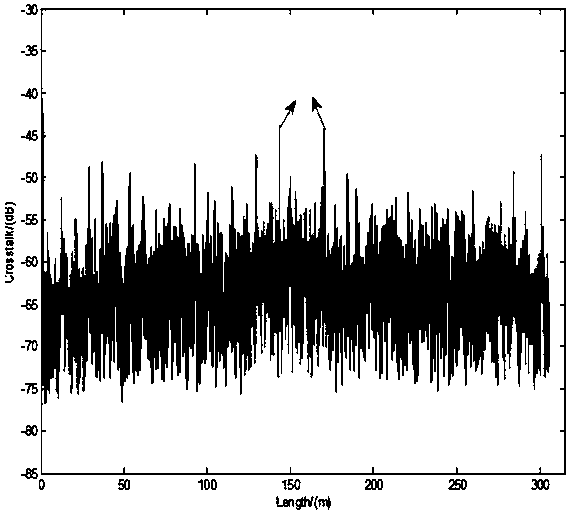
[0034] It should be noted that, the embodiment of the present invention introduces the optical path principle of a typical interferometric fiber optic gyroscope, such as figure 1 As shown, the optical path of a typical interferometric fiber optic gyro includes a light source (superluminescent light-emitting diode), a photodetector, a coupler, a polarizer, a Y waveguide, and a polarization-maintaining fiber ring, where a1, a2, a3, b1, and b2 represent The welding points between the pigtails of each device, m1, m2, and m3 represent the welding points ...


PUM


Abstract

The invention relates to an optic fiber gyroscope testing method and device, a storage medium and computer equipment. The method includes acquiring corresponding parameters of a light source in a light path of an optic fiber gyroscope, optical fiber butt fusion points, a polarization maintaining optical fibre segment and a polarizer; acquiring a polarization crosstalk measurement result of a polarization maintaining optical fibre loop in the optic fiber gyroscope; and according to the corresponding parameters of the light source in the light path, the optical fiber butt fusion points, the polarization maintaining optical fibre segment and the polarizer, and according to the polarization crosstalk measurement result of the polarization maintaining optical fibre loop, operating an optical path transmission physical model set in advance to acquire quality parameters of the optic fiber gyroscope. Through the method, quality of the optic fiber gyroscope can be evaluated before the optic fiber gyroscope is subjected to a high- and low-temperature actual measurement, and the gyroscope quality before actual measurement is assessed in advance and can be adopted as a reference for actual measurement to prevent a phenomenon that a large error in an actual measurement process is unaware, thus increasing testing precision and ensuring accuracy of a testing result.

Description

technical field [0001] The invention relates to the technical field of fiber optic gyroscopes, in particular to a testing method, device, storage medium and computer equipment for fiber optic gyroscopes. Background technique [0002] The interferometric fiber optic gyroscope is an angular velocity sensor used for inertial navigation. It has broad development and application prospects in many military and civilian fields such as inertial guidance, vehicle positioning, and underground detection. In the actual production and application process, due to the fluctuation of the degree of polarization of the light source, the defects of the welding points between the pigtails of the components in the optical path, the unsatisfactory extinction ratio of the Y waveguide, and the large number of polarization crosstalk points in the polarization maintaining fiber ring, and with the external As the ambient temperature changes, the intensity and position of these polarization crosstalk p...

Claims


Application Information

Patent Timeline
IPC IPC(8): G01C25/00
CPCG01C25/00
Inventor 姚晓天
Owner 苏州光环科技有限公司
Why Eureka
Try Eureka