

Calculation method for electric field under crossing area of alternating current-direct current power transmission line
A technology of AC and DC power transmission and line crossing, applied in computing, instrumentation, data processing applications, etc., can solve problems such as lack of accurate and fast algorithms, avoid large-scale numerical calculation, reduce the amount of calculation, and achieve high accuracy. Effect
Active Publication Date: 2018-02-16
POWERCHINA HEBEI ELECTRIC POWER SURVEY & DESIGN INST CO LTD
View PDF3 Cites 10 Cited by
- Summary
- Abstract
- Description
- Claims
- Application Information
AI Technical Summary
Problems solved by technology
There is currently no accurate and fast algorithm for the calculation of the electric field and ion flow field below the crossing area of ultra-high voltage DC transmission lines and AC transmission lines
Method used
View moreImage
Smart ImageViewing Examples

Examples
Embodiment Construction
Login to View More PUM
 Abstract
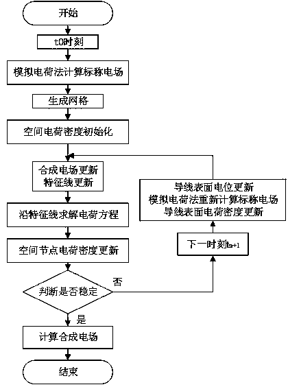
The invention discloses a calculation method for an electric field under the crossing area of an alternating current-direct current power transmission line, and relates to the field of the high-voltage power transmission technology and electromagnetic field calculation. The calculation method comprises the following steps that: calculating the nominal electric field of each space joint at a certain moment, initializing space charge density, calculating a synthesis electric field, applying a method of characteristics to update space charge density distribution on an electric field line, calculating space charge density corresponding to different moments on the space node, and carrying out convergence judgment so as to obtain the electric field under the crossing area of the alternating current-direct current power transmission line. The calculation method disclosed by the invention has the characteristics of accurate calculation result and small calculation workload.
Description
Technical field The invention relates to the field of high-voltage power transmission technology and electromagnetic field calculation, and is used for calculating the electric field under the line when an ultra-high voltage AC transmission line and a DC transmission line cross over. Background technique Due to the current passing through the transmission line, the transmission line itself will generate a nominal electric field in its surrounding space, and due to the corona phenomenon of the transmission line, the air around the transmission line will ionize to form charged particles. When a corona occurs in an AC transmission line, due to the periodic change in the polarity of the conductor voltage, the ions generated by the air ionization caused by the corona discharge in the first half cycle are almost all pulled back to the conductor due to the voltage polarity change in the second half cycle , So that the ionized ions are basically bound near the wire, and there are no ch...
Claims
Login to View More Application Information
Patent Timeline
 Patent Type & Authority Applications(China)
IPC IPC(8): G06Q50/06
CPCG06Q50/06
Inventor 闫建兴王炜王延杰
Owner POWERCHINA HEBEI ELECTRIC POWER SURVEY & DESIGN INST CO LTD