Battery pack shell for new energy vehicle and manufacturing method of battery pack shell

A new energy vehicle and manufacturing method technology, applied in battery pack parts, circuits, electrical components, etc., can solve the problems of reducing shell wall thickness, large mold cost, heavy weight, etc., to ensure structural strength and durability, The effect of large structural design space and low mold cost

Inactive Publication Date: 2018-02-16
GUANGZHOU XIAOPENG MOTORS TECH CO LTD
View PDF7 Cites 18 Cited by
  • Summary
  • Abstract
  • Description
  • Claims
  • Application Information

AI Technical Summary

Problems solved by technology

[0003] For the existing technology of the new energy vehicle battery pack housing, it is more common to weld steel sheet metal parts, such as the invention patent disclosed in CN105501041 A, but the weight of the housing in this manufacturing method is relatively heavy, and it is resistant to Corrosion performance is not good; some use aluminum alloy gravity casting, but this method has many casting defects, poor mechanical properties, and thicker wall thickness is not conducive to the lightweight of the battery pack shell; some use advanced casting technology such as aluminum alloy vacuum High-pressure casting, CN106694841A disclosed invention patent, the battery pack casing adopts this technology to reduce casting defects to a certain extent, reduce the shell wall thickness to 3mm, yield strength ≥ 140Mpa, tensile st

Method used


Image

  • Battery pack shell for new energy vehicle and manufacturing method of battery pack shell
  • Battery pack shell for new energy vehicle and manufacturing method of battery pack shell
  • Battery pack shell for new energy vehicle and manufacturing method of battery pack shell

Examples


Embodiment Construction

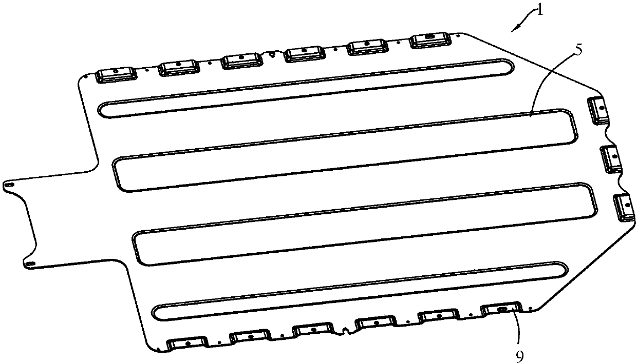
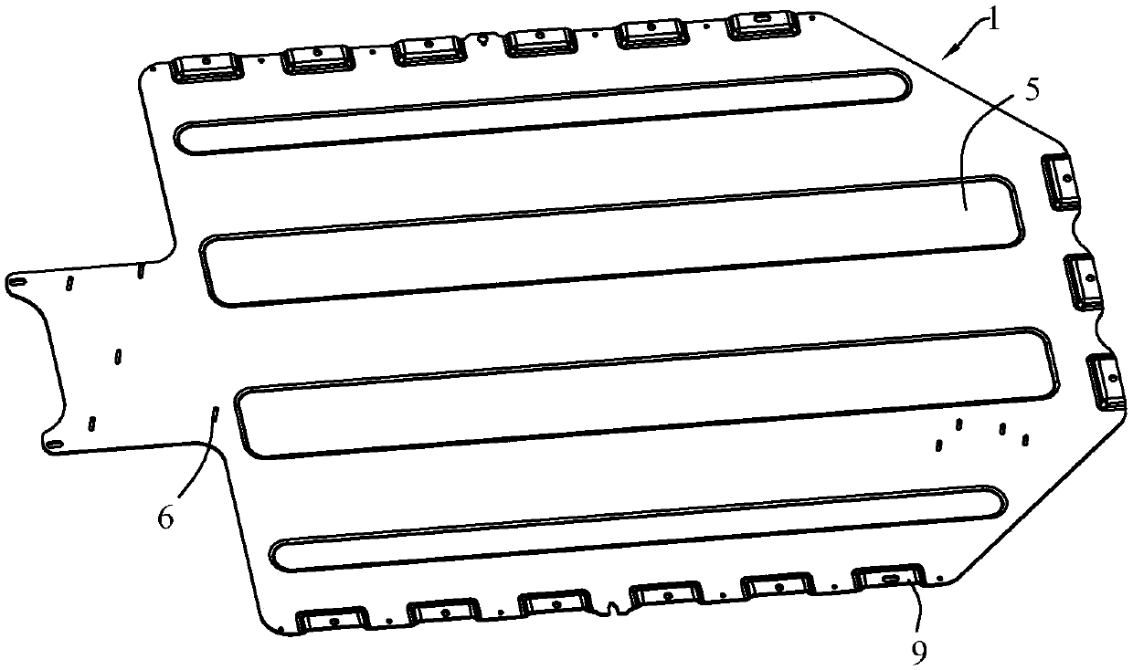
[0034] refer to Figure 1 to Figure 8 , which shows the specific structure of the preferred embodiment of the present invention. The structural characteristics of each component of the present invention will be described in detail below.

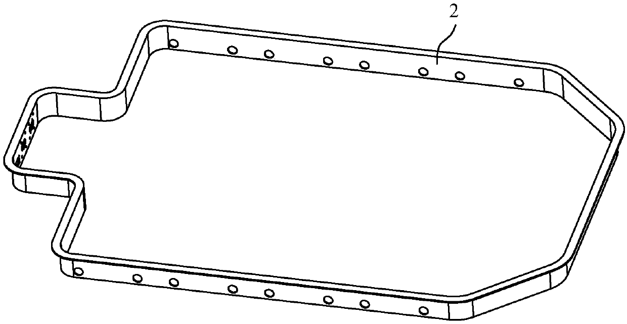
[0035] The present invention provides a new energy vehicle battery pack housing, which includes a bottom plate 1, a side frame 2 and an upper cover 3, the bottom plate 1 is a stamped metal sheet, and the side frame 2 is an extruded metal profile. The bent ends of the metal profiles are butted to form a side frame 2 with a closed-loop structure. The bottom of the side frame 2 forms the connection end of the bottom plate, and the top of the side frame forms the connection end of the upper cover. The bottom connection end of the side frame 2 is connected to the bottom plate 1 welding, and form a battery containing cavity 4 inside, and the upper cover 3 cooperates with the connecting end of the upper cover to cover the battery containing cavity...


PUM


Abstract

The invention discloses a battery pack shell for a new energy vehicle and a manufacturing method of the battery pack shell for the technical field of battery packs. The battery pack shell comprises abottom plate, a side frame and an upper cover, wherein a stamped and formed metal plate is adopted by the bottom plate; an extruded metal section is adopted by the side frame; the metal section is bent and then the end part is docked to form the side frame with a closed loop structure; a bottom plate connection end is formed at the bottom of the side frame; an upper cover connection end is formedat the top of the side frame; the bottom plate connection end of the side frame is connected with the bottom plate in a welding manner and a battery pack accommodating cavity is formed in the side frame; and the upper cover is matched with the upper cover connection end to cover the battery pack accommodating cavity. A whole plate stamping form is adopted by the bottom plate of the battery pack shell, so that the connection reliability of the bottom plate and a vehicle body floor is ensured while the stiffness is improved; and the section is short in mold making period and low in price and thestructure is large in design space, so that the side frame is formed by bending the section and carrying out tailor-welding, the side frame is connected with the bottom plate in a welding manner andthe welding strength and the strength reliability of the battery pack can be effectively ensured.

Description

technical field [0001] The invention is used in the technical field of battery packs, and in particular relates to a new energy vehicle battery pack shell and a manufacturing method thereof. Background technique [0002] New energy vehicles are developing rapidly under the promotion of national policies. As an important part of electric passenger vehicles, battery packs are generally installed under the body floor, and the battery pack shell bears the weight of the internal battery module and BMS control system. Currently, The cruising range of domestic pure electric vehicles is about 200-300 kilometers, and the weight of the battery pack is about 300 kg. With the continuous increase of cruising range, the weight of the battery pack is also increasing. Durability and other performance are crucial to the safety of the vehicle. On the other hand, the weight of the battery pack shell will also affect the energy density of the battery pack and the cruising range of the vehicle. ...

Claims


Application Information

Patent Timeline
IPC IPC(8): H01M2/10B23P15/00H01M50/249
CPCB23P15/00H01M50/20Y02E60/10
Inventor 杨海张风波王建宜黄锦腾
Owner GUANGZHOU XIAOPENG MOTORS TECH CO LTD
Why Eureka
Try Eureka