Bucket for swinging rotor of centrifugal separator

A centrifugal separator and rotor technology, which is applied to the barrel field of the swing rotor to ensure the sealing performance and easy handling.

Active Publication Date: 2018-02-16
KUBOTA SEISAKUSHOKK
View PDF6 Cites 4 Cited by
  • Summary
  • Abstract
  • Description
  • Claims
  • Application Information

AI Technical Summary

Problems solved by technology

Note that this transport operation cannot b

Method used


Image

  • Bucket for swinging rotor of centrifugal separator
  • Bucket for swinging rotor of centrifugal separator
  • Bucket for swinging rotor of centrifugal separator

Examples


Embodiment Construction

[0047] The following will refer to Figure 1 to Figure 12 An embodiment of a bucket for an oscillating rotor of a centrifuge according to the invention will be described in detail.

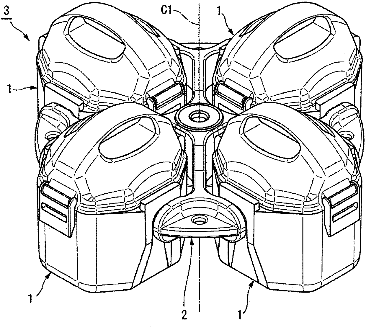
[0048] figure 1 The four barrels 1 shown in are supported by a rotor yoke 2 . The four buckets 1 and the rotor yoke 2 form an oscillating rotor 3 of a centrifuge (not shown). Rotor yoke 2 around figure 1 The axis of rotation indicated by the dashed-dotted line C1 in the center rotates. The axis of rotation C1 extends in the vertical direction.

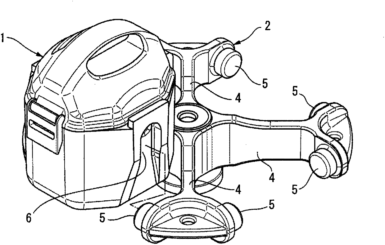
[0049] Such as figure 2 As shown in , the rotor yoke 2 includes four arms 4 each extending in the horizontal direction. Each of the distal end portions of the arms 4 is provided with a trunnion pin 5 . The trunnion pins 5 support the tub 1 rotatably and detachably, and are each formed in a cylindrical shape. Trunnion pins 5 are rotatably fitted from below in trunnion pin grooves 6 provided in both side portions of each tub 1 (see figure 2 )middl...


PUM


Abstract

The present invention comprises: a bottomed cylindrical bucket main body (11); a cover main body (21) (cover); packing (22) (seal member); and a pair of attachment mechanisms (34) that detachably attach the cover main body (21) to the bucket main body (11). The cover main body (21) includes: a lid (24) which has clip fixing parts (31) (parts to be pressed) and which covers an opening (11a) of thebucket main body (11); and a handle (25) which is formed integrally with the lid (24). The handle (25) is laid between the pair of clip fixing parts (31). Formed between the lid (24) and the handle (25) is a handle recess (36) (hole) which opens toward the outside of the cover main body (21) and which divides the lid (24) and the handle (25). Due to this configuration, the present invention provides a bucket for a swinging rotor of a centrifugal separator for which the sealing property is ensured during centrifugal processing or transportation and which can be easily transported.

Description

field of invention [0001] The invention relates to a bucket for an oscillating rotor of a centrifuge including a protective cover. Background technique [0002] A oscillating rotor is provided as a rotor for a centrifuge. The oscillating rotor is formed by a rotor yoke and a barrel. Tubes each containing a sample are inserted into the barrel, and the barrel is formed in a bottomed cylindrical shape, and is detachably and pivotably attached to the rotor yoke. When the tubes are held in the racks, the tubes are contained in the buckets. As the rotor rotates, the barrel is swung by centrifugal force up to an angle of 0 to 90°. [0003] For example, as described in Patent Document 1, as this conventional type of tub, there is provided a tub including a protective cover for sealing the inside of the tub. The reason the inside of the barrel is sealed is to prevent poisonous bacteria, poisonous substances, etc. from leaking out of the barrel, and to prevent other substances fro...

Claims


Application Information

Patent Timeline
IPC IPC(8): B04B5/02B04B7/02
CPCB04B5/0421B04B2005/0435
Inventor 吉田英树
Owner KUBOTA SEISAKUSHOKK
Why Eureka
Try Eureka