Electric vehicle position detection system
A technology for detection systems and electric vehicles, applied in radio wave measurement systems, electric vehicles, control drives, etc., can solve the problems of unknown trains and narrow reading range of preferred tags, and achieve low-cost effects
- Summary
- Abstract
- Description
- Claims
- Application Information
AI Technical Summary
Problems solved by technology
Method used
Image


Examples
no. 1 Embodiment approach
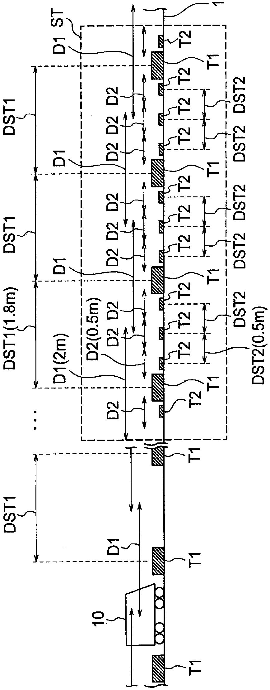
[0021] figure 1 It is a figure which shows an example of the structure of the electric vehicle position detection system of 1st Embodiment. The electric vehicle position detection system according to the first embodiment includes a plurality of first tags T1, a plurality of second tags T2, and readers 11, 12 (refer to figure 2 ) and database 13 (see figure 2 ). The plurality of first tags T1 are tags having the same configuration as each other. The plurality of second labels are labels having the same configuration as each other. On the other hand, the first tag T1 and the second tag T2 have mutually different structures.
[0022] The first and second tags T1 and T2 are, for example, RFID tags, and may be either active tags or passive tags. However, when system costs, installation costs, and the like are considered, the first and second tags T1 and T2 are preferably passive tags that do not require a power source.
[0023] The plurality of first tags T1 are installed a...
no. 2 Embodiment approach
[0050] Figure 4 It is a figure which shows an example of the structure of the electric vehicle position detection system of 2nd Embodiment. In 2nd Embodiment, the installation interval DST2 of 2nd tag T2 is wider than this installation interval in 1st Embodiment. For example, the installation interval DST2 of the 2nd tag T2 is about 1 meter. Other configurations of the second embodiment may be the same as the corresponding configurations of the first embodiment.
[0051] By setting the installation interval DST2 of the second label T2 wider, as Figure 4 As shown, the ID readable ranges of the two adjacent second tags T2 are separated from each other. Therefore, a space region SP is generated between the ID readable ranges of the adjacent two second tags T2 between the two adjacent first tags T1. The space area SP is a range in which the ID of the second tag T2 cannot be read between two adjacent first tags T1.
[0052] The readers 11 and 12 cannot read the ID of the sec...
no. 3 Embodiment approach
[0055] Figure 5 It is a figure which shows an example of the structure of the electric vehicle position detection system of 3rd Embodiment. The electric vehicle position detection system of the third embodiment further includes a plurality of third tags T3 installed along the track 1 in the station ST and having mutually different IDs.
[0056] The third tag T3 is, for example, an RFID tag, and may be either an active tag or a passive tag. However, in consideration of system costs, installation costs, etc., it is preferable that the third tag T3 is also a passive tag that does not require a power source, like the first and second tags T1 and T2.
[0057] The plurality of third tags T3 are installed along the line 1 and have mutually different identifiers. That is, each of the plurality of third tags T3 has a unique identifier, and the tag can be identified by reading the identifier.
[0058] The third tag T3 has a third range D3 as an ID readable range. The third range D3...
PUM
 Abstract
Description
Claims
Application Information
 - R&D
- Intellectual Property
- Life Sciences
- Materials
- Tech Scout
- Unparalleled Data Quality
- Higher Quality Content
- 60% Fewer Hallucinations
Browse by: Latest US Patents, China's latest patents, Technical Efficacy Thesaurus, Application Domain, Technology Topic, Popular Technical Reports.
© 2025 PatSnap. All rights reserved.Legal|Privacy policy|Modern Slavery Act Transparency Statement|Sitemap|About US| Contact US: help@patsnap.com