Separating-preventing ligating clip

A ligation clip and anti-dropping technology, which is applied in the field of medical devices, can solve the problems of vascular clips falling off, easily damaged and broken at the connection, and difficult to control the quality of the arc-shaped hole. Solid and reliable results

Pending Publication Date: 2018-02-23
SURGAID MEDICAL XIAMEN CO LTD
View PDF9 Cites 4 Cited by
  • Summary
  • Abstract
  • Description
  • Claims
  • Application Information

AI Technical Summary

Problems solved by technology

The clip body of these blood vessel clips can produce elastic deformation, and an arc-shaped hole is set at the junction of the two clips. When the blood vessel needs to be clamped, the inside and outside of the arc-shaped hole are deformed by a large torque, especially the arc-shaped The outer side is easily subjected to a large bending stress, and the connection is easily damaged and broken, which will cause the vascular clip to fall off. On the other hand, because the sides of the arc are very thin, it is difficult to control the quality of the arc hole stably during the production process.

Method used


Image

  • Separating-preventing ligating clip
  • Separating-preventing ligating clip
  • Separating-preventing ligating clip

Examples


Embodiment 1

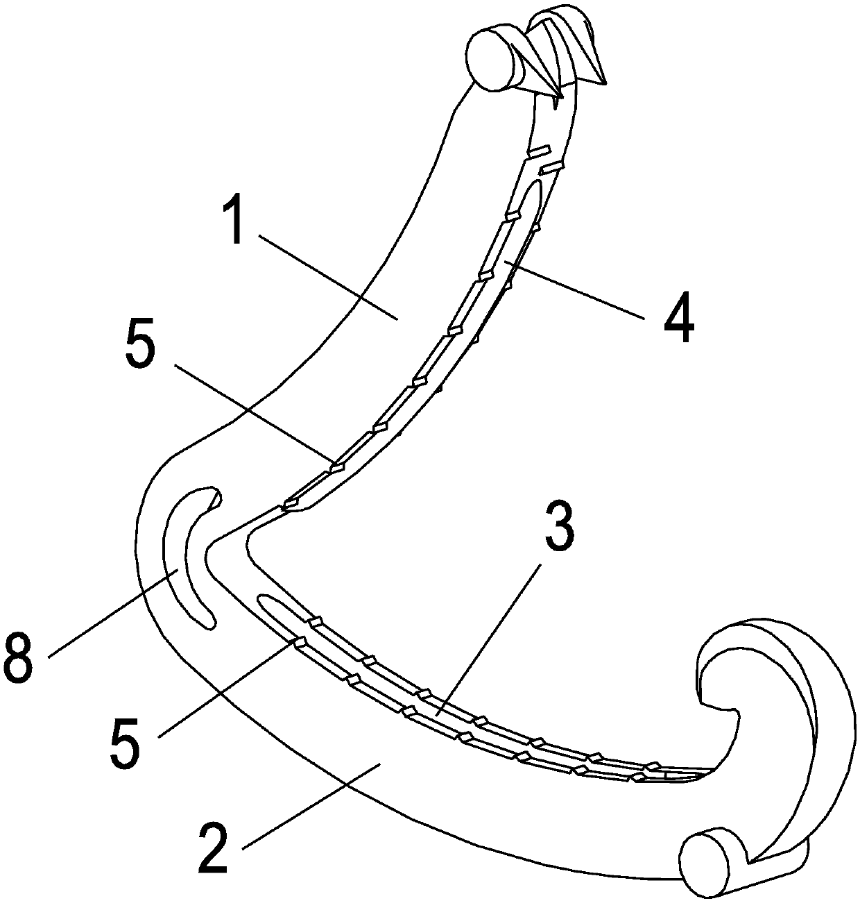
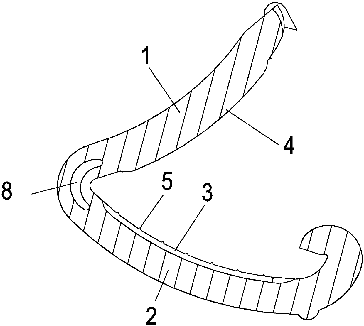
[0034] Such as Figure 1-3 As shown, the clamping surface of the upper clamping arm 1 is provided with an anti-slip protrusion 4 , and the clamping surface of the lower clamping arm 2 is provided with an anti-slip long groove 3 .

[0035] Preferably, the anti-slip long groove 3 is located in the middle of the clamping surface, the clamping surfaces on both sides of the anti-slip long groove 3 are provided with anti-slip lines 5, the anti-slip protrusion 4 is located in the middle of the clamping surface, and the two sides of the anti-slip protrusion 4 are clamped Anti-slip lines 5 are provided on the surface.

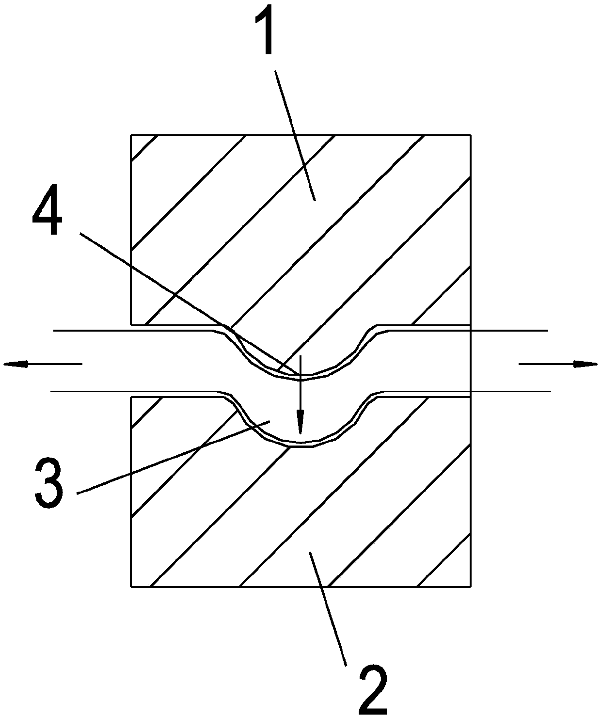
[0036] When the upper clamping arm 1 and the lower clamping arm 2 are clamped together, the anti-slip long groove 3 and the anti-slip protrusion 4 are buckled together, which not only increases the clamping area, but also makes the clamping tissue on different surfaces, which can effectively prevent the lateral slipping of blood vessels.

Embodiment 2

[0038] Such as Figure 4-6 As shown, the clamping surface of the upper clamping arm 1 is provided with an anti-slip long groove 3 , and the clamping surface of the lower clamping arm 2 is also provided with an anti-slip long groove 3 .

[0039] Preferably, the long anti-slip groove 3 is located in the middle of the clamping surface, and the two sides of the long anti-slip groove 3 are provided with anti-slip lines 5 on the clamping surface.

[0040] When the upper clamping arm 1 and the lower clamping arm 2 are clamped together, the two anti-skid long grooves 3 buckle to form an inner cavity. When clamping, the tissue expands in the inner cavity to form a lateral block, which can effectively increase the clamping force and prevent the blood vessel from slipping laterally.

Embodiment 3

[0042] Such as Figure 11-12 As shown, the anti-slip long groove 3 is provided with one, which extends from the front side of the clamping surface of the clamp arm to the rear side; the corresponding anti-slip protrusion 4 is also provided with one, which extends from the front side of the clamping surface of the clamp arm to the rear side. rear side.

[0043] Described upper jig arm 1 and lower jig arm 2, wherein one is wide arm 9, and another is narrow arm 10; Anti-slip long groove 3 is set on wide arm 9, and anti-slip protrusion 4 (anti-slip protrusion 4 is set on narrow arm 10) Consistent with the width of the clamping surface of the narrow arm 10). The upper side of the narrow arm 10 is embedded in the anti-skid slot 3 of the wide arm 9 .

[0044] Chamfers 6 are provided on both sides of the clamping surface of the narrow arm 10 , and both inner surfaces of the long anti-slip groove 3 are inclined surfaces 7 matching with the chamfers 6 .

[0045] The bottom surface of...


PUM


Abstract

The invention relates a separating-preventing ligating clip. The separating-preventing ligating clip comprises an upper clip arm and a lower clip arm, wherein the tail ends of the upper clip arm and the lower clip arm are fixedly connected, and the front ends of the upper clip arm and the lower clip arm are fixed through a locking structure; for the upper clip arm and the lower clip arm, one clamping face is provided with an anti-skid elongated slot extending along the length direction of the clip arms, the other clamping face is provided with an anti-skid bulge extending along the length direction of the clip arm, and the anti-skid elongated slot and the anti-skid bulge are arranged in a corresponding manner. The invention aims at providing the separating-preventing ligating clip which can prevent the tissue from separating horizontally and is firm and reliable in ligating. The separating-preventing ligating clip has the advantages that the clamping faces of the upper clip arm and thelower clip arm are provided with the anti-skid elongated slot and the anti-skid bulge which are matched with each other, when the upper clip arm and the lower clip arm are in clamping, the anti-skidelongated slot and the anti-skid bulge are buckled, thus the clamping area is increased, meanwhile, the clamped issue is positioned on different faces, so that the horizontal sliding of the blood vessel can be prevented.

Description

technical field [0001] The invention relates to the field of medical instruments, in particular to a detachment-preventing ligation clip. Background technique [0002] Hemostasis technology is one of the core technologies of basic surgical operations. Surgical operations on any part of the human body involve bleeding and hemostasis. Traditional methods such as ligation, suture, packing, and thermal hemostasis on the hemostatic site still play an important role, and vascular clips, hemostatic gauze, and staplers developed on this basis are also widely used. [0003] Vascular ligation clip is a surgical hemostatic consumable for deep bleeding of small and medium blood vessels that has emerged in recent years, and is used to block blood flow or clamp occluded blood vessels. Most of the existing vascular ligation clips are made of silver or alloy, followed by medical plastics, such as silver clips, titanium clips, tantalum clips, and hemolok clips. The clip body of these blood...

Claims


Application Information

Patent Timeline
Patent Type & Authority Applications(China)
IPC IPC(8): A61B17/122
CPCA61B17/122A61B2017/00778A61B2017/12004
Inventor 林志雄莫易凡林聪杰胡林锋邱木旺
Owner SURGAID MEDICAL XIAMEN CO LTD
Why Eureka
Try Eureka